A-XIII
An
hang
·
Ap
pend
ix
nex
e
s
3.9
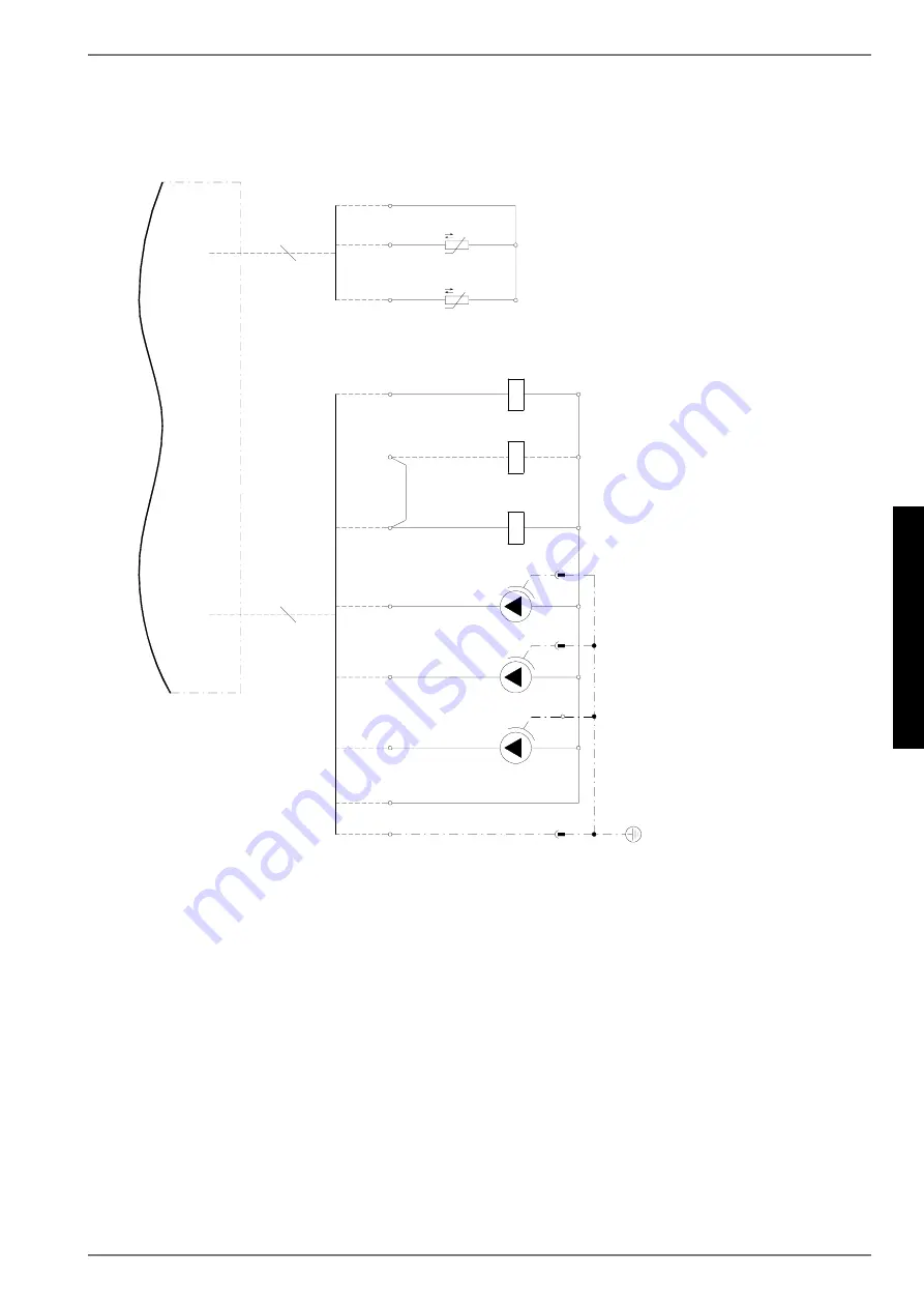
3.9 Anschlussplan / Circuit diagram / Schéma électrique HWK 332
0
;
$
.
G
5
*1
'
1
3(
(
3
Page 1: ...HPM Tour hydraulique combin e avec gestionnaire de PAC Tour hydraulique combin e sans gestionnaire de PAC Montage und Gebrauchsanweisung Deutsch English Fran ais Instructions d installation et d utili...
Page 2: ......
Page 3: ...rmepumpenmanager DE 3 4 Transport DE 3 5 Aufstellung DE 3 5 1 Allgemein DE 3 5 2 Schall DE 3 6 Montage DE 4 6 1 Allgemein DE 4 6 2 Heizungsseitiger Anschluss DE 4 6 3 Elektrischer Anschluss DE 4 7 Inb...
Page 4: ...chluss des Hydro Towers sind die ent sprechenden VDE EN und IEC Normen einzuhalten Au er dem m ssen die Anschlussbedingungen der Versorgungsnetz betreiber beachtet werden Beim Anschlie en der Heizungs...
Page 5: ...sport zum endg ltigen Aufstellungsort sollte mit Holz rost erfolgen Das Grundger t bietet einerseits die Transport m glichkeit mit Hubwagen Sackkarre o ACHTUNG Hydro Tower und Transportpalette sind mi...
Page 6: ...bsbereit sind arbeitet die Frost schutzfunktion des Reglers Bei Au erbetriebnahme der W rme pumpe oder Stromausfall ist die Anlage zu entleeren Bei W r mepumpenanlagen an denen ein Stromausfall nicht...
Page 7: ...ssigkeit Raumtempera tur haben Es ist empfehlenswert den W rmeaustauscher ent gegen der normalen Durchflussrichtung zu sp len Um zu verhindern dass s urehaltiges Reinigungsmittel in den Heizungsanlag...
Page 8: ...Beachten Sie dass der Platzbedarf f r Rohranschluss Bedienung und Wartung gr er ist 1920 x 740 x 950 1920 x 740 x 950 4 2 Kippma mm 2000 2000 4 3 Ger teanschl sse f r W rmeerzeuger Zoll 1 1 4 AG FL 1...
Page 9: ...p manager EN 3 4 Transport EN 3 5 Installation EN 3 5 1 General EN 3 5 2 Sound EN 3 6 Assembly EN 4 6 1 General EN 4 6 2 Heating system connection EN 4 6 3 Electrical connection EN 4 7 Start up EN 5 7...
Page 10: ...cting the hydro tower to the power supply the rele vant VDE EN and IEC standards must be fulfilled Any further connection requirements stipulated by the mains supply network operator must also be obse...
Page 11: ...its final installation location The basic device can be transported with a lift truck a pushcart or similar ATTENTION The hydro tower is to be fixed to the transport pallet with screws 5 Installation...
Page 12: ...heat pumps which are exposed to frost The frost protection function of the heat pump controller is active whenever the controller and the heat circulating pump are ready for operation The system has t...
Page 13: ...acid solution for cleaning purposes However if cleaning needs to be performed more frequently a 5 formic acid solu tion should be used In either case the cleaning fluid should be at room temperature W...
Page 14: ...operation and maintenance 1920 x 740 x 950 1920 x 740 x 950 4 2 Tilting dimension mm 2000 2000 4 3 Device connections for heat generator inches 1 1 4 external thread flange 1 1 4 external thread flang...
Page 15: ...pe chaleur FR 3 4 Transport FR 3 5 Installation FR 3 5 1 G n ralit s FR 3 5 2 Bruit FR 4 6 Montage FR 4 6 1 G n ralit s FR 4 6 2 Raccordement c t chauffage FR 4 6 3 Branchements lectriques FR 5 7 Mise...
Page 16: ...s et autres lieux r sidentiels Lors de la construction et de la r alisation de la tour hydraulique combin e toutes les normes CE et prescriptions DIN et VDE concern es ont t respect es voir d claratio...
Page 17: ...t de r gulation lectronique facile utiliser Il commande et surveille l ensemble de l installation de chauffage en fonction de la temp rature ext rieure la production d eau chaude sanitaire et les disp...
Page 18: ...effectuer les raccordements c t chauffage il convient de rincer l installation de chauffage pour liminer les impuret s restes de mat riau d tanch it ventuellement pr sents ou autres Une accumulation...
Page 19: ...i re doit tre effectu e par un service apr s vente agr par le construc teur Le respect de cette clause permet une prorogation de la ga rantie sous certaines conditions voir Garantie 7 2 Pr paratifs Av...
Page 20: ...le raccord PE de la languette d embo tement de l anode anticorrosion 2 brancher l amp rem tre 0 0 50mA entre le raccord PE et la languette d embo tement 3 valuation du degr d usure de l anode anticorr...
Page 21: ...ordement des tuyaux la commande et l entretien 1920 x 740 x 950 1920 x 740 x 950 4 2 Hauteur appareil bascul mm 2000 2000 4 3 Raccordements du g n rateur de chaleur pouce s 1 1 4 filet ext joint plat...
Page 22: ...FR 8 Fran ais 11...
Page 23: ...lan Circuit diagram Sch ma lectrique HWK 332 Econ A VIII 3 6 Legende Legend L gende HWK 332 Econ A IX 3 7 Steuerung Control Commande HWK 332 A XI 3 8 Last Load Charge HWK 332 A XII 3 9 Anschlussplan C...
Page 24: ...SHU F OLQGHU FRYHU OHFWULF KHDWLQJ HOHPHQW N 5HWXUQ WR WKH KHDW SXPS H WHUQDO WKUHDG IODW VHDOLQJ ORZ IURP WKH KHDW SXPS H WHUQDO WKUHDG IODW VHDOLQJ LQWHUQDO WKUHDG RU RSWLRQDO LPPHUVLRQ KHDWHU FRQQH...
Page 25: ...Z UDWH LQ P K pELW G HDX GH FKDXIIDJH HQ P K XUFKIOXVV LQ P K ORZ UDWH LQ P K pELW HQ P K XUFKIOXVV LQ P K ORZ UDWH LQ P K pELW HQ P K HL NUHLV KHDWLQJ FLUFXLW FLUFXLW GH FKDXIIDJH 6WXIH HYHO 1LYHDX 6...
Page 26: ...iagrams Sch mas lectriques 3 1 Steuerung Control Commande HWK 332 Econ 9 9 12 12 12 5 7 5 7 1 1 95 9 WHUP 9 1 1 12 12 12 12 1 12 12 12 12 1 12 1 12 1 1 5 G 1 1 5 5 1 1 1 1 1 3 5 7 7 DDDD EEEE FFFF GGG...
Page 27: ...A V Anhang Appendix Annexes 3 2 3 2 Steuerung Control Commande HWK 332 Econ 1 1 5 1 1 5 1 12 1 12 1 12 12 12 1...
Page 28: ...A VI Anhang Appendix Annexes 3 3 3 3 Last Load Charge HWK 332 Econ 7 67 75 7 67 75 7 67 75 1 3 9 1 3 1 3 9 1 3...
Page 29: ...Sch ma lectrique HWK 332 Econ 9 9 12 12 12 5 7 5 7 1 1 95 9 WHUP 9 1 1 12 12 12 12 1 12 12 12 12 1 12 1 12 1 1 7 7 5 G 5 G 1 1 5 5 1 1 1 1 1 3 1 3 9 3 5 7 7 DDDD EEEE FFFF GGG HHH IIII JJJ 1 5 G 5 1 1...
Page 30: ...A VIII Anhang Appendix Annexes 3 5 3 5 Anschlussplan Circuit diagram Sch ma lectrique HWK 332 Econ 1 1 1 12 1 12 1 12 12 12 5 G 1 G 5 5 1 1 1 5 0 3 1 0 3 1 3 9 0 1 7 7 7 1 1 W 1 7 1...
Page 31: ...rfernanzeige Remote fault indicator lamp Voyant de t l d tection de pannes J1 Spannungsversorgung N1 Voltage supply N1 Alimentation en tension N1 J2 3 Analogeing nge Analogue inputs Entr es analogiqu...
Page 32: ...rbindungsleitung Manager W rmepumpe 25 V AC Connecting cable plug Heat pump manager 25 V AC Connecteur c ble de raccordement gestionnaire pompe chaleur 25 V AC X13 2 Stecker Verbindungsleitung Manager...
Page 33: ...A XI Anhang Appendix Annexes 3 7 3 7 Steuerung Control Commande HWK 332 0 0 0 0 0 0 G 5 5 G 5 5 1 1 3 3 3 3 3...
Page 34: ...A XII Anhang Appendix Annexes 3 8 3 8 Last Load Charge HWK 332 7 67 75 7 67 75 7 67 75 1 3 9 1 3 1 3 9 1 3...
Page 35: ...A XIII Anhang Appendix Annexes 3 9 3 9 Anschlussplan Circuit diagram Sch ma lectrique HWK 332 0 0 0 0 0 0 G 5 5 G 5 5 1 1 3 1 3 3 3 3...
Page 36: ...tstemperaturbegrenzer E9 Safety temperature limiter E9 Limiteur de temp rature de s curit E9 K20 Sch tz E10 11 Contactor E10 11 Contacteur E10 11 K20 2 Sch tz E10 12 Contactor E10 12 Contacteur E10 12...
Page 37: ...ische W rmepumpenheizungsanlage f r einen Heizkreis Puffer und Warmwasserspeicher Mono energy heat pump heating system for one heating circuit buffer tank and hot water cylinder Installation de chauff...
Page 38: ...meverbraucher Heat consumer Consommateur de chaleur Temperaturf hler Temperature sensor Sonde de temp rature R ckschlagklappe Check valve Clapet anit retour W rmepumpe Heat pump Pompe chaleur Hydro To...
Page 39: ...A XVII Anhang Appendix Annexes 4 2...
Page 40: ...sales service addres ses please refer to the Installation and Operating Instructions for Heat Pumps Pour les conditions de garantie et les adresses SAV se r f rer aux instructions de montage et d tili...