9
electric shock or damage to persons.
1.
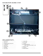
Remove the firebox out of the cabinet.
2.
From the back of the unit remove the screws (16 on the
EF2870 and 12 on the EF2570) that secure the back
panel to the firebox.
3. Locate and disconnect the two tabs, by squeezing the
tabs securing the IR sensor to the unit, with needle
nose pliers.
4. Trace the wire back to the control board and discon-
nect.
5. Connect the new IR sensor and reassemble.
WARNING:
Ensure wires do not come in contact with
moving parts by securing wires in wiring tie wraps.
THERMISTOR REPLACEMENT
Tools required:
Phillips head screwdriver
WARNING:
If the fireplace was operating prior to ser
-
vicing allow at least 10 minutes for the heating elements
to cool off to avoid accidental burning of skin.
WARNING:
Disconnect circuit power before attempt-
ing any maintenance or cleaning to reduce the risk of
electric shock or damage to persons.
1.
Remove the firebox out of the cabinet.
2.
From the back of the unit remove the screws (16 on the
EF2870 and 12 on the EF2570) that secure the back
panel to the firebox.
3. Remove the top panel by removing the two screws on
either end.
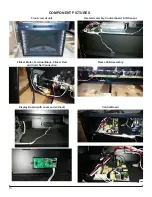
4. Locate and remove the thermistor from the unit, se-
cured by one screw.
5. Trace the wire back to the control board and discon-
nect.
6. Connect the new thermistor and reassemble.
WARNING:
Ensure wires do not come in contact with
moving parts by securing wires in wiring tie wraps.
HEATER ASSEMBLY REPLACEMENT
Tools required:
Phillips head screwdriver
WARNING:
If the fireplace was operating prior to ser
-
vicing allow at least 10 minutes for the heating elements
to cool off to avoid accidental burning of skin.
WARNING:
Disconnect circuit power before attempt-
ing any maintenance or cleaning to reduce the risk of
electric shock or damage to persons.
1.
Remove the firebox out of the cabinet.
2.
From the back of the unit remove the screws (16 on the
EF2870 and 12 on the EF2570) that secure the back
panel to the firebox.
3. Remove the top panel by removing the two screws on
either end.
4. The heater assembly is attached to the unit with two
brackets (one at the front of the unit and the other at
the back) with two screws on each. Remove the heater
assembly from the unit.
5. Disconnect the wiring connections, at the control board,
and install the new heater assembly.
6. Reattach the wiring and reassemble.
WARNING:
Ensure wires do not come in contact with
moving parts by securing wires in wiring tie wraps.
SWITCHBOARD REPLACEMENT
Tools required:
Phillips head screwdriver
WARNING:
If the fireplace was operating prior to ser
-
vicing allow at least 10 minutes for the heating elements
to cool off to avoid accidental burning of skin.
WARNING:
Disconnect circuit power before attempt-
ing any maintenance or cleaning to reduce the risk of
electric shock or damage to persons.
1.
Remove the firebox out of the cabinet.
2.
From the back of the unit remove the screws (16 on the
EF2870 and 12 on the EF2570) that secure the back
panel to the firebox.
3. Remove the top panel by removing the two screws on
either end.
4. Locate and remove the switch board from the unit,
secured by two screws.
5. Disconnect the wiring connection and install the new
switchboard.
6. Connect the new switchboard and reassemble.
WARNING:
Ensure wires do not come in contact with
moving parts by securing wires in wiring tie wraps.
CONTROL BOARD REPLACEMENT
Tools required:
Phillips head screwdriver
WARNING:
If the fireplace was operating prior to ser
-
vicing allow at least 10 minutes for the heating elements
to cool off to avoid accidental burning of skin.
WARNING:
Disconnect circuit power before attempt-
ing any maintenance or cleaning to reduce the risk of
electric shock or damage to persons.
1.
Remove the firebox out of the cabinet.
2.
From the back of the unit remove the screws (16 on the
EF2870 and 12 on the EF2570) that secure the back
panel to the firebox.
3. Remove the top panel by removing the two screws on
either end.
4. Locate and remove the control board from the unit,
secured by four screws.
5. Disconnect the wiring connection, noting their original
locations, and install the new switchboard.
6. Connect the new switchboard and reassemble.
WARNING:
Ensure wires do not come in contact with
moving parts by securing wires in wiring tie wraps.


