


8
FLICKER MOTOR REPLACEMENT
Tools required:
Phillips head screwdriver
WARNING:
If the fireplace was operating prior to ser
-
vicing allow at least 10 minutes for the heating elements
to cool off to avoid accidental burning of skin.
WARNING:
Disconnect circuit power before attempt-
ing any maintenance or cleaning to reduce the risk of
electric shock or damage to persons.
1.
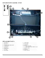
Remove the firebox out of the cabinet.
2.
From the back of the unit remove the screws (16 on the
EF2870 and 12 on the EF2570) that secure the back
panel to the firebox.
3.
Locate the flicker rod and gently move it horizontally to
the right, to disengage the end from the rubber grom-
met on the flicker motor.
4.
Locate the flicker motor retaining bracket
5. Disconnect the two screws, from the outside of the unit,
that secure the mounting bracket to the side, to remove
the flicker motor.
6.
Remove the flicker motor from the bracket and trace
the wires to the wire connectors or terminal block
(mounted on the bottom of the unit).
7. Disconnect the wiring connections noting their original
locations, from the terminal block, and replace with the
wires from the new motor.
8. Reassemble in the reverse order as above.
FLAME LED REPLACEMENT
Tools required:
Phillips head screwdriver
WARNING:
If the fireplace was operating prior to
servicing allow at least 10 minutes for light bulbs and
heating elements to cool off to avoid accidental burning
of skin.
WARNING:
Disconnect circuit power before attempt-
ing any maintenance or cleaning to reduce the risk of
electric shock or damage to persons.
1.
Remove the firebox out of the cabinet.
2.
From the back of the unit remove the screws (16 on the
EF2870 and 12 on the EF2570) that secure the back
panel to the firebox.
3.
Locate the flicker rod and gently move it horizontally to
the right, to disengage the end from the rubber grom-
met on the flicker motor.
4.
Locate the flame LED strip.
5. Remove the 2 retaining screws.
6. Disconnect the wiring connection and install the new
LED board.
7. Reassemble in the reverse order as above.
CORD SET REPLACEMENT
Tools required:
Phillips head screwdriver
WARNING:
If the fireplace was operating prior to ser
-
vicing allow at least 10 minutes for the heating elements
to cool off to avoid accidental burning of skin.
WARNING:
Disconnect circuit power before attempt-
ing any maintenance or cleaning to reduce the risk of
electric shock or damage to persons.
1.
Remove the firebox out of the cabinet.
2.
From the back of the unit remove the screws (16 on the
EF2870 and 12 on the EF2570) that secure the back
panel to the firebox.
3. Locate and disconnect the power cord wiring connec-
tions, on the terminal block, noting their original loca-
tions.
4. With needle nose pliers grasp the power cord strain
relief grommet from inside the right rear of the panel
and push while twisting to remove.
5. Pull the power cord out through the hole in side of the
unit.
6. Insert the new power cord through the hole and con-
nect all of the wiring connections in their original loca-
tions.
7. Install the power cord strain relief grommet on the
replacement cord.
8. Reassemble in the reverse order as above.
DISPLAY BOARD REPLACEMENT
Tools required:
Phillips head screwdriver
WARNING:
If the fireplace was operating prior to ser
-
vicing allow at least 10 minutes for the heating elements
to cool off to avoid accidental burning of skin.
WARNING:
Disconnect circuit power before attempt-
ing any maintenance or cleaning to reduce the risk of
electric shock or damage to persons.
1.
Remove the firebox out of the cabinet.
2.
From the back of the unit remove the screws (16 on the
EF2870 and 12 on the EF2570) that secure the back
panel to the firebox.
3. Locate and remove the display board cover, secured
with two screws.
4. Remove the two screws securing the display board to
the unit.
5. Trace the wire back to the control board and discon-
nect.
6. Connect the new control board and reassemble.
WARNING:
Ensure wires do not come in contact with
moving parts by securing wires in wiring tie wraps.
IR SENSOR REPLACEMENT
Tools required:
Phillips head screwdriver
Needle Nose Pliers
WARNING:
If the fireplace was operating prior to ser
-
vicing allow at least 10 minutes for the heating elements
to cool off to avoid accidental burning of skin.
WARNING:
Disconnect circuit power before attempt-
ing any maintenance or cleaning to reduce the risk of