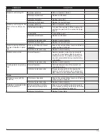
Dimplex EF2570 Service Manual Download Page 12

12 

PROBLEM

CAUSE

SOLUTION

PART NUMBER

General

Circuit breaker trips or fuse 

blows when unit is turned 

on

Short in unit wiring.

Trace wiring in unit.

Improper circuit current rating

Additional appliances may exceed the current 

rating of the circuit breaker or fuse.  Plug unit 

into another outlet or install unit on a dedi-

cated 15 amp circuit.

Lights dim in room while the 

unit is on

Unit is drawing close to circuit 

current rating

Move the unit to another outlet or install unit 

on a dedicated 15 amp circuit

Power cord gets warm

Normal Operation

The power cord may get slightly warm to the 

touch when the heater is on

Defective power cord

Replace power cord if cord gets hot to the 

touch.

Appearance

Fireplace does not turn on 

with manual controls

Improper operation

Refer to Operation Section

No incoming voltage from the 

electrical wall socket

Check Fuse/Breaker Panel

Loose wiring

Check wiring connections

Defective switchboard

Replace the switchboard

Defective control board

Replace the control board 

Fireplace does not turn on 

with the Remote Control

Improper operation

Refer to Operation Section

The batteries in the remote con-

trol are dead.

Install new battery into the remote control.

Defective remote control

Replace the remote control

Defective IR sensor

Replace IR sensor

Defective control board

Replace the control board 

Display is not working

Loose wiring

Check wiring connections

Defective display board

Replace the display board

Defective control board

Replace the control board 

Display is showing “88”

Unit requires resetting

Turn all of the controls to Off and unplug the 

unit from the wall for 5-10 minutes, then plug 

back in

Display has a “EEE” 

showing

Loose connection of the 

thermistor

Check wiring connection

Defective thermistor

Replace the thermistor

Flame Frozen

Loose wiring

Check wiring connections

Defective Flicker Motor

Replace Flicker Motor

Flame is not visible

Loose wiring

Check wiring connections

LED flame assembly is not 

working

Replace LED flame assembly

Defective control board

Replace the control board 

Flame Shudder

Defective Flicker Motor

Replace Flicker Motor

Media is not lighting up

Loose wiring

Check wiring connections

Ember LED light assembly is not 

working

Replace ember LED light assembly

Light leaking around the log 

set (if applicable)

Log set not positioned properly

Check log set for proper fit

TROUBLESHOOTING GUIDE

Summary of Contents for EF2570

Page 1: ...ATION Always read this manual first before attempting to service this fireplace For your safety always comply with all warnings and safety instructions contained in this manual to prevent personal inj...

Page 2: ...the risk of fire serious injury or death Operation 3 Exploded Parts Diagram EF2870 5 Replacement Parts EF2870 5 Exploded Parts Diagram EF2570 6 Replacement Parts EF2570 6 Wiring Diagram EF2870 7 Wirin...

Page 3: ...Retailer for recy cling advice in your area OPERATION Figure 1 WARNING This electric firebox must be properly installed before it is used The manual controls for the unit are located in the top right...

Page 4: ...is used The manual controls for the unit are located in the top right hand corner Figure 3 NOTE Press any button to activate the On Screen display before making any changes A Standby Turns the unit O...

Page 5: ...er Rod 3 Heater Assembly with cutout 4 Control Board 5 Switchboard 6 Display Board 7 Thermistor 8 Flame LED s REPLACEMENT PARTS 9 Ember LED s 10 Down Lights 11 Cord Set 12 Front GlassAssembly comes wi...

Page 6: ...Rod 3 Heater Assembly with cutout 4 Control Board 5 Switchboard 6 Display Board 7 Thermistor 8 Flame LED s 9 Ember LED s 10 Cord Set 11 Front Glass comes with screws to attach to unit 12 Remote Contro...

Page 7: ...RWH LVSOD 17 703 1 M M THERMISTOR SWITCHBOARD DISPLAY REMOTE MOTOR HEATING ELEMENTS CUTOUT WIRING DIAGRAM THERMISTOR SWITCHBOARD FLAMES M M 1 17 703 LVSOD 5HPRWH ODPH 1 02725 1 H RDUG 7 IXVH 1 37 3 5...

Page 8: ...llips head screwdriver WARNING If the fireplace was operating prior to ser vicing allow at least 10 minutes for the heating elements to cool off to avoid accidental burning of skin WARNING Disconnect...

Page 9: ...ter assembly is attached to the unit with two brackets one at the front of the unit and the other at the back with two screws on each Remove the heater assembly from the unit 5 Disconnect the wiring c...

Page 10: ...NENT PICTURES Heater Assembly Control board IR Sensor Flame LED Assembly Front view of unit Flicker Motor Terminal Block Flicker Rod and Cord Set Connection Display Board with cover and without Contro...

Page 11: ...w of unit Heater Assembly and Control board Flicker Motor Terminal Block and Flicker Rod Flame LED Assembly Display Board with cover and without Control Board and Switch Board EF2870 COMPONENT PICTURE...

Page 12: ...Operation Section The batteries in the remote con trol are dead Install new battery into the remote control Defective remote control Replace the remote control Defective IR sensor Replace IR sensor D...

Page 13: ...e heater assembly Replace heater assembly Heater emits an odor Normal Operation Normal operation is when the heater emits an odor for a brief period after the heater is initially turned on The heater...

Reviews: