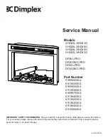
Dimplex DF26DWC-PRO Service Manual Download Page 6


www.dimplex.com

Wiring Diagram

Logset or Media Bed LEDs

On log models only

M

AC / DC

120V / 12V

~

IR

REMOTE

M

L

LOGSET ASSEMBLY

FLAME BASE OR MEDIA BED RBG STRIP

FLAME LED LIGHTS

FLICKER 

MOTOR

BLOWER 

MOTOR

IR EYE/DISPLAY/CAPACITIVE 

TOUCH CONTROL BOARD

 MAIN CONTROL 

BOARD

G

POWER

SUPPLY

NTC

CUTOUT

N

XHD23 MOD 0-A 

XHD26 MOD 0-B 

XHD28 MOD 0-A
ALL DF-PRO

XHD23 MOD B 

XHD26 MOD C 

XHD28 MOD B

Summary of Contents for DF26DWC-PRO

Page 1: ...0XXX 6909850XXX 6913830XXX 6909970XXX 6913840XXX 6913820XXX 6913830XXX 6913840XXX 6910090XXX 7401050100R05 IMPORTANT SAFETY INFORMATION Always read this manual first before attempting to service this...

Page 2: ...e user to the risk of fire serious injury or death XHD Replacement Parts List 1 3 XHD Replacement Parts List 2 4 DF PRO Replacement Parts List 5 Wiring Diagrams 6 Accessing Top Components 7 Accessing...

Page 3: ...Ds XHD23L XHD26L 3001880100RP XHD28L 3001880200RP 11 Media LED Strip XHD23G 3001570100RP XHD26G 3001570700RP XHD28G 3001570300RP 12 Flame Screen XHD23 5902580400RP XHD26 5902580500RP XHD28 5902580600R...

Page 4: ...RP XHD28L 3001880200RP XHD33L 3001880300RP 11 Media LED Strip XHD23G 3001570100RP XHD26G 3001570700RP XHD28G 3001570300RP XHD33G 2 3001960100RP 12 Flame Screen XHD23 5902580400RP XHD26 5902580500RP XH...

Page 5: ...70700RP DF28DWC PRO 3001570300RP 12 Flame Screen DF26 PRO 5902580500RP DF28 PRO 5902580600RP 13 Logset DF26L PRO 0442220100RP DF28L PRO 0442300100RP 14 Media Tray DF26DWC PRO 0442280100RP DF28DWC PRO...

Page 6: ...V IR REMOTE M L LOGSET ASSEMBLY FLAME BASE OR MEDIA BED RBG STRIP FLAME LED LIGHTS FLICKER MOTOR BLOWER MOTOR IR EYE DISPLAY CAPACITIVE TOUCH CONTROL BOARD MAIN CONTROL BOARD G POWER SUPPLY NTC CUTOUT...

Page 7: ...p cover flat so that the attached components are acces sible Accessing Bottom Components Tools Required Phillips head screwdriver WARNING If the firebox was operating prior to servicing allow at least...

Page 8: ...r ring Cut the cable ties as needed to remove the wires 3 With pliers grasp the power cord strain relief grommet from inside the back of the bottom panel and push while twisting to remove 4 Install th...

Page 9: ...ents on page 8 NOTE It is recommended to take a picture of the wiring connections on the main control board and heater assembly prior to starting to ensure that all wires are reconnected to the correc...

Page 10: ...th pliers Pull on both wires to ensure a strong connection 9 Repeat the process for the 4 remaining wires ensuring that all wires are paired by colour in each connector 10 Attach new flicker motor to...

Page 11: ...c LED holder bar and remove the screw on either side 2 total Figure 7 3 Disconnect the two cables that lead to the LED strips 4 The LED holder can now be removed 5 Release the LED strip from the clips...

Page 12: ...that affixes the thermistor to the firebox 8 Affix the new thermistor to the firebox using the provided cable tie 9 Reassemble the firebox Flame Screen Replacement Tools Required Phillips head screwdr...

Page 13: ...teries see Maintenance section Defective remote control Replace remote control Defective touchpad Replace touchpad Firebox turns off shortly after being powered on Defective power supply Replace power...

Page 14: ...ive noise when the heater is on Buildup of dust debris in the heater assembly Ensure that the exterior intake louvers and firebox cavity are free of dust debris Defective heater assembly Replace heate...

Reviews: