9
Installation Instructions
Please read all instructions before installing.
WARNING:
Failure to install the cassette as instructed below may result in damage to the equipment and or may
expose the user to the risk of fire, serious injury, illness or death.
WARNING:
Construction and electrical outlet wiring must comply with local building codes and other applicable
regulations.
CAUTION:
It is recommended that during drywall installation and finishing the media plate be installed with the
provided bag to prevent dust and debris from entering the unit.
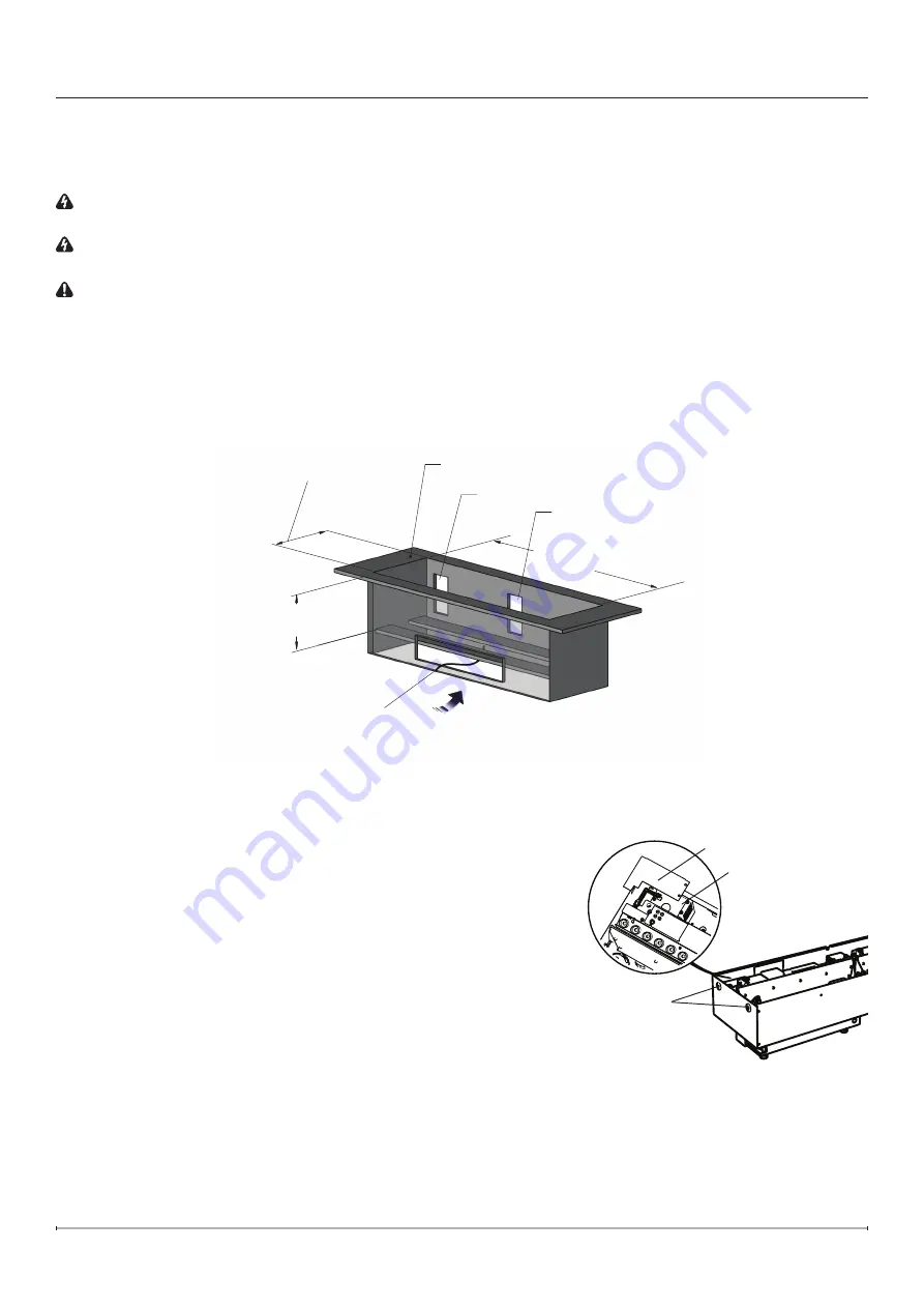
1. Use studs to frame an enclosure with the minimum internal/opening dimensions shown in Figure 3. Note that the
media plate (supplied) and log set (optional, sold separately) require different opening widths.
!
NOTE:
When preparing the opening for the unit ¼" (6.4 mm) of clearance should be maintained from each
surface to ensure easy installation.
Exit for Water Supply
Fresh Air Inlet
CDFI500-PRO: 40 in² (258 cm²)
CDFI1000-PRO: 80 in² (516 cm²)
Exit for Electrical
Installation Surface
Air Path
CDFI500-PRO: 20
⅜
in (518mm)
CDFI1000-PRO: 40
⅜
in (1025mm)
Log Set: 14¼ in (362mm)
Media Plate: 12¼ in (311mm)
Adjustable from
9 in to 9½ in
(229 mm to 241 mm)
Figure 3
Cable Plate
Electrical Cover Plate
Holes for
securing to
framing
Figure 4
Installation
2. If connecting to plumbing, complete the water connection
according to the instructions in the ‘Cassette Plumbing’ section
(page 10).
3. In the back left corner of the unit, locate and remove the electrical
cover plate, by removing the two securing screws (Figure 4).
4. Complete the wiring according to instructions in the ‘Electrical
Installation’ section (page 11). Reinstall the electrical cover plate
after completing wiring.
!
NOTE:
If using the optional power cord
(CDFI-PLUGKIT, sold separately), follow the instructions provided
with the kit.
5. Install the unit into the rough-in framing ensuring that the unit is
resting on two framing sills, one at the front and one at the back
or a level surface. Ensure an air opening is maintained.
6. Level the housing - right to left and front to back, using the
adjustable feet on the bottom of the unit.
7. Secure the unit to the permanent framing on either end through a
minimum of two holes (Figure 4).


