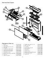
Dimplex BF8000ST Service Manual Download Page 14

14

shock or damage to persons.

Remove the firebox from the mantel.

1. 

Lay unit on its back.

2. 

Remove the 12 Philips screws that fasten the bottom 

3. 

cover to the rest of the firebox.  There are:  two (2) 

screws on each side; two (2) screws on the back panel 

(you may have to tip the bottom of the fireplace up 

if it is laying on its back), four (4) screws in the front 

directly under the control panel; and two (2) screws 

on the bottom of the fireplace (Figure 8).  The bottom 

panel is now free to be removed.

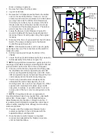
Locate the Remote Control Receiver (Figure 20) 

4. 

mounted underneath the log set support panel and 

disconnect the six (6) wiring clips noting their original 

locations. 
Disconnect the three (3) wire leads from the 3-Position 

5. 

Switch. (The wires are hard-wired to the Remote 

Control Receiver) (Figure 20)

!

NOTE:  

A flat head screwdriver can be used to gently 

pry between the end of the connectors and the switch to 

release the wires.

Pull the Antenna wire through the bottom of the 

6. 

chassis.
Locate the three (3) LED indicator lights from inside the 

7. 

bottom assembly of the firebox. (Figure 18)

!

NOTE: 

Using a flathead screwdriver, gently push on the 

rear edge of the plastic bushing surrounding each LED and 

push each LED out from the front of the control panel.

Clear any silicon that may be present and firmly grasp 

8. 

the sheathed ends of the wires leading to each LED 

and remove the plastic bushing from each LED.  Each 

LED and paired wires can be fed back through the front 

control panel and into the bottom assembly area.
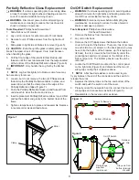
The Remote Control Receiver is fastened to the 

9. 

underside of the ember bed support by four (4) 

mounting studs, one in each corner (Figure 20).  Either 

squeeze each mounting stud’s clasp, using needle 

nose pliers, to release, or use side cutters to cut and 

remove each of the four corner mounting studs on the 

board.  

!


NOTE:

  If mounting studs are cut, replacement 

mounting studs will need to be inserted from underneath 

ember bed.  Follow steps 1 - 5 of Partially Reflective 

Glass Replacement procedure on Page 9 to do this.  It 

is recommended to attempt to release the control board 

without cutting mounting studs, although new mounting 

studs are provided.

Properly orient the replacement Remote Control 

10. 

receiver and adhere to the control panel with the 

supplied/existing mounting studs.  
Once the remote control receiver is mounted, 

11. 

reconnect and reassemble the fireplace in reverse 

order as described above.

Figure 20

3-Position Switch

LEDs (3)

All Hard-

wired Ends

3-Position

Switch

Wires (3)

Antenna

Wire

Remote

Control

Receiver

Mounting

Studs (4)

Summary of Contents for BF8000ST

Page 1: ...plex North America Limited 1367 Industrial Road Cambridge ON Canada N1R 7G8 1 888 346 7539 www dimplex com IMPORTANT SAFETY INFORMATION Always read this manual first before attempting to service this...

Page 2: ...cker Rod Replacement 11 Thermostat Control Replacement 12 Heater Assembly Replacement 12 Power Cord Replacement 13 Remote Control Replacement If Applicable 13 Troubleshooting Guide 15 Always use a qua...

Page 3: ...odor is a normal condition caused by initial heating of internal heater parts and will not occur again A D C F E B Figure 2 3 Position Switch Level 1 Flame only Level 2 Flame and low heat Level 3 Flam...

Page 4: ...in the battery holder 2 Close the battery cover 3 Battery must be recycled or disposed of properly Check with your Local Authority or Retailer for recycling advice in your area Figure 3 Battery Cover...

Page 5: ...t of fireplace 7 Remove flicker rod by sliding flicker rod to the left away 8 from the flicker motor and lifting out Remove light bracket for easier access to light bulbs 9 Unscrew bulbs counter clock...

Page 6: ...8 3000250100RP Remote Control Receiver Mod 0 A 9 3000430800RP Power Cord 10 4100040200RP Single Lamp holder 11 2500150300RP Double Lamp holder 2 in unit 12 2500400300RP Mirror no brick 13 5901210100R...

Page 7: ...7 Wiring Diagram 3 Stage Remote MOD 0 A Units Power Cord Heater Assembly Thermostat 3 Position Switch Light Dimmer Control Flame Speed Control Terminal Block Remote Control Receiver...

Page 8: ...8 Wiring Diagram No Remote MOD B F Units Power Cord Heater Assembly Thermostat On Off Switch Heater On Off Switch Light Dimmer Control Flame Speed Control Terminal Block...

Page 9: ...ten clamps back into place and reassemble fireplace 9 in reverse order as described above On Off Switch Replacement Warning If unit was operating prior to servicing allow at least 5 minutes for light...

Page 10: ...e 7 Light Dimmer Replacement Warning If unit was operating prior to servicing allow at least 5 minutes for light bulbs and heating element to cool off to avoid accidental burning of skin Warning Disco...

Page 11: ...new mounting studs are provided Properly orient the new potentiometer and control board 8 and re connect all of the wiring connections Reassemble in the reverse order as above 9 Flame Speed Control Re...

Page 12: ...directly under the control panel and two 2 screws on the bottom of the fireplace Figure 8 The bottom panel is now free to be removed Locate the Thermostat Control mounted on the control 4 panel on the...

Page 13: ...the fireplace Figure 8 The bottom panel is now free to be removed Locate and disconnect the two 2 power cord wire 4 connections one from the middle of the three 3 connectors on the On Off Switch the...

Page 14: ...each LED and push each LED out from the front of the control panel Clear any silicon that may be present and firmly grasp 8 the sheathed ends of the wires leading to each LED and remove the plastic b...

Page 15: ...e Light Dimmer Components Appearance Fireplace does not turn on Manu ally Improper operation Refer to Operation Section No incoming voltage from the electrical wall socket Check Fuse Breaker Panel Loo...

Page 16: ...uring or operation Defective Heater Assembly Replace Heater Assembly Heater fan turns on but heater lacks heat Improper operation Refer to Operation Section Loose wiring Trace wiring in unit Defective...

Reviews: