


10
www.dimplex.com
3-POSITION SWITCH REPLACEMENT
Tools Required:
Phillips head screwdriver.
WARNING:
If the fireplace was operating prior to
servicing allow at least 10 minutes for light bulbs and
heating elements to cool off to avoid accidental burning
of skin.
WARNING:
Disconnect circuit power before attempt-
ing any maintenance or cleaning to reduce the risk of
electric shock or damage to persons.
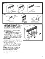
1.
Remove the firebox trim by placing your hand on the
grille section, grasping the sides of the trim and pulling
forward, away from the firebox, releasing the retainer
clips.
2.
Remove the firebox from the mantel.
3. Remove the 6 retaining screws on the edges along the
top cover: 2 on the left; 2 on the right; 2 on the back.
Remove the top, placing it upside down on the top of
the unit being careful not to damage any of the wiring.
4. Locate the 3-Position Switch mounted on the front top
panel and disconnect the wiring clips and connections
noting their original locations.
5. Depress the retainer clips on the rear of the switch and
push the switch out of the rear cover.
6. Properly orient the new 3-Position Switch and connect
all of the wiring clips and connections.
7. Align the top cover with the cabinet assembly and se-
cure with 6 retaining screws.
8.
Place the firebox in the mantel.
9.
Place trim back on firebox by opening grille, grasping
both sides of trim, and hook the trim down into the trim
slots.
!
NOTE:
The trim slots are located on the front surface
of the firebox.
10. Close the grille.
THERMOSTAT CONTROL
REPLACEMENT
Tools Required:
Phillips head screwdriver
Flat Head Screwdriver
WARNING:
If the fireplace was operating prior to
servicing allow at least 10 minutes for light bulbs and
heating elements to cool off to avoid accidental burning
of skin.
WARNING:
Disconnect circuit power before attempt-
ing any maintenance or cleaning to reduce the risk of
electric shock or damage to persons.
1.
Remove the firebox trim by placing your hand on the
grille section, grasping the sides of the trim and pulling
forward, away from the firebox, releasing the retainer
clips.
2.
Remove the firebox from the mantel.
3. Remove the 6 retaining screws on the edges along the
top cover: 2 on the left; 2 on the right; 2 on the back.
Remove the top, placing it upside down on the top of
the unit being careful not to damage any of the wiring.
4. Locate the thermostat control mounted on the front top
panel and disconnect the wiring clips and connections
noting their original locations.
!
NOTE:
Using a flat head screwdriver gently pry be
-
tween the end of the connector and the controller to release
the wires.
5. Pull off the thermostat control knob to expose the
mounting screws.
6. Remove the mounting screws and remove the thermo-
stat control.
7. Properly orient and mount the new heater thermostat
control and connect all of the wiring connections.
8. Reassemble in the reverse order as above.
HEATER ASSEMBLY REPLACEMENT
Tools Required:
Phillips head screwdriver
Flat Head Screwdriver
WARNING:
If the fireplace was operating prior to
servicing allow at least 10 minutes for light bulbs and
heating elements to cool off to avoid accidental burning
of skin.
WARNING:
Disconnect circuit power before attempt-
ing any maintenance or cleaning to reduce the risk of
electric shock or damage to persons.
1.
Remove the firebox trim by placing your hand on the
grille section, grasping the sides of the trim and pulling
forward, away from the firebox, releasing the retainer
clips.
2.
Remove the firebox from the mantel.
3. Remove the 6 retaining screws on the edges along the
top cover: 2 on the left; 2 on the right; 2 on the back.
Remove the top, placing it upside down on the top of
the unit being careful not to damage any of the wiring.
4. Locate the heater assembly mounted on the top panel
and disconnect the wiring clips and connections noting
their original locations.
!
NOTE:
Using a flat head screwdriver gently pry be
-
tween the end of the connector and the heater to release
the wires.
5. Turn the top back over, remove the 6 heater mounting
screws, being careful to support the heater assembly
as you do this.
6.
Remove the 4 screws attaching the vent/deflector
around the elements; 2 top and 2 bottom.
7. Properly orient the new heater assembly and connect
all of the wiring connections.
8. Reassemble in the reverse order as above.