


3
Fig. 7
Before switching on
Remove the fuel effect (two screws) and check that the lamps and
flicker rotors are positioned correctly – see Fig. 8, page 4.
The flicker rotors should sit horizontally on their pins and spin
freely without fouling their mounting brackets. If necessary, adjust
the bracket by bending slightly.
Refit the fuel effect by inserting the front edge first, then
secure it with the two screws.
Ensure that all packing items are removed (read any warning
labels carefully) and that the fuel effect and radiant elements are
positioned correctly, otherwise damage may occur.
Operation
When you are certain that you have completed the installation,
plug in and switch on at the wall socket.
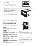
Controls - see Fig. 7
Fuel effect
The fuel effect will be lit all the time that the heater is connected to
the power supply, even if the heat selector switches are in the OFF
position. The flicker rotors should begin to rotate after a minute
or so.
The lamps will go out only when the heater is switched off at the
wall socket or unplugged.
Radiant elements
You have a choice of low heat (two elements, 1332W) or high heat
(three elements, 1998W). Both settings have electronic
temperature control - see below.
A switch is set to ON when the red dot is visible.
Low heat setting
Press switch 1 to ON. Two elements will glow and, when the
temperature selected on the electronic control dial 3 is reached,
one of the elements will automatically turn off, switching back on if
the temperature falls.
See also ‘Electronic economiser temperature control ’
4
5
•
3
1
2
4. Remove the fuel effect by releasing the two screws securing it
at either end – see Fig. 5
Lift and hang the heater on the two screw heads fixed to the
wall.
Mark the position of the third fixing hole, accessible with the fuel
effect removed.
Remove the heater from the wall and drill and plug the third
hole.
5. Replace the heater on the wall and use the third screw to fix the
heater firmly to the wall, routing the mains lead through the
appropriate cutout at the rear of the heater base (see Fig. 2).
NB If the heater is to be fixed to the wall in the floor standing
position, it may be necessary to either:
(i) cut away the skirting board where the heater will be fixed
or
(ii) provide suitable battens on the wall to which the fixing points
of the heater may be secured to provide clearance for the
thickness of the skirting board – see Fig. 6.
Fig. 5
Fig. 6
High heat setting
Set switches 1 and 2 to ON. All three elements will glow and,
when the temperature selected on the electronic control dial 3 is
reached, two of the elements will automatically turn off, switching
back on if the temperature falls.
The fire can be returned to low heat setting by pressing switch 2
to OFF.
See also ‘Electronic economiser temperature control ’ below.
Electronic economiser temperature control
This sensitive output control 3 will switch the radiant heater
elements ON and OFF to accurately maintain the level of comfort
that you have selected.
Select low or high radiant setting – then turn the control dial to 7;
when the room reaches a comfortable level of warmth, turn the
dial down until the electronically controlled elements switch off.
The control dial should be left at this setting; the electronic control
will then switch the elements ON and OFF as needed to maintain
your chosen comfort level.