01/2016
ABOUT MANUAL
Before installing and using the camera, please read this manual carefully.Be sure to keep it handy for future reference.
ANALOG HIGH DEFINITION
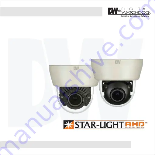
SnapIt Indoor Dome Camera
DWC-D4783WDDWC-D4783WTIR
Page 1: ...6 ABOUT MANUAL Before installing and using the camera please read this manual carefully Be sure to keep it handy for future reference ANALOG HIGH DEFINITION SnapIt Indoor Dome Camera DWC D4783WD DWC D4783WTIR ...
Page 2: ...erature may rise to high levels Cleaning To remove dirt from the case moisten a soft cloth with a soft detergent solution and wipe Mounting Surface The material of the mounting surface must be strong enough to support the camera FCC COMPLIANCE This equipment has been tested and found to comply with the limits for a Class B digital device pursuant to part 15 of the FCC rules These limits are design...
Page 3: ... OSD Menu Troubleshooting Warranty Information Specifications Features Parts and Descriptions Dimensions Inside the Box Installation Instructions Connecting to Monitors 11 Gang Box Installation Instructions 4 5 6 7 8 9 10 12 13 26 27 28 29 30 31 Adjusting the Camera Angle ...
Page 4: ... DWC D4783WTIR Models Smart DNR 3D Digital Noise Reduction Highlight Masking Exposure HME True Day Night Mechanical IR Cut Filter DWC D4783WTIR Models Auto Sensing 24VAC 12VDC with Line Lock Secondary Video BNC Output While UTP in use Easy Icon Driven OSD Menu with Built in Joystick Programmable Privacy Zones Auto Gain Control AGC Back Light Compensation BLC Dynamic Range Compressor DRC Reveals Lo...
Page 5: ...Set Screw 5 PARTS DESCRIPTION Vent Cables BNC UTP RS485 Control Borad Upper Case Bubble Dome Cover Tilt Stopper Screw Joystick Test Monitor Cable Slot Lens ...
Page 6: ...6 DIMENSIONS IN MILLIMETERS IN 89 108 TOP VIEW 40 5 56 3 96 8 108 4 25 3 81 1 59 2 22 4 25 3 50 ...
Page 7: ...7 INSIDE THE BOX Included with your camera Camera Template Sheet Cables Screw Plastic Anchor 2pcs Test Monitor Calbe User s Manual ...
Page 8: ... Use the camera s mounting template or your camera and drill the necessary mounting holes to the mounting surface 3 Pull Wires through and make connections 4 Mount the camera to the mounting surface using the included screws 5 Adjust the camera s lens position by using the 3 Axis gimbal 6 Snap the camera dome over the camera module to complete the installation ...
Page 9: ...ot holes required Drill holes into the drywall and insert the drywall mounts Secure the wall mount to the wall using the mounting screws Attach the base of the camera to the wall mount with the smaller machine screws Adjust the camera lens and snap the dome cover over the camera module 1 2 3 4 5 ...
Page 10: ...10 INSTALLATION INSTRUCTIONS NOTE Screws required for electrical junction boxes are not supplied These screws are readily available at an electrical supply store Philips 8 32 x 0 75 2S ...
Page 11: ... Dual Voltage Auto Polarity Detection and Protection All cameras are equipped with a second video output for on site configuration NOTE Make sure the UTP COAX switch is set to the proper connection If the switch is set for example to UTP but the camera is connected via Coax the video from the camera will appear black Right Left Up UTP 2ND COAX Down 2nd Video Output ...
Page 12: ...12 ADJUSTING THE CAMERA ANGLE Rotation 360 Panning 360 75 ...
Page 13: ...CA CAM TITLE FRAME RATE FREQUENCY EXIT JUMP SAVE EXIT EXIT DEFECT DET ON LANGUAGE COLOR GAIN EXIT JUMP EXIT JUMP SENSITIVITY 0 10 DET WINDOWS EXIT JUMP POLYGON EXIT JUMP MANUAL AUTO OFF HME BLC WDR OFF ON OFF x2 x32 OFF LOW MIDDLE HIGH SAVE EXIT EXIT AUTO AUTO EX PRESET MANULAL 0 20 SAVE EXIT EXIT AUTO COLOR BW EXTERN 0 20 0 20 SAVE EXIT EXIT 0 10 MIRROR OFF ON 0 45 0 75 OFF ON SAVE EXIT EXIT OFF ...
Page 14: ...number the brighter the image will appear Shutter Set the shutter speed to AUTO Manual or FLC Flicker less mode If AUTO is selected select from the following options NORMAL Set when the camera is installed in an indoor environment DEBLUR Set when the camera is installed in an outdoor envirnment Select FLC if the camera is experiencing some flickering in the image If Manual is selected set the shut...
Page 15: ...Right button on OSD joystick can be set manually SCANNING If the focus is not adjusted iwhen Half Model is selected change the Scanning value to Full Mode to adjust the focus ONEPUSHAF Run the Auto Focus at the camera s current FoV SYNC TDN When enabled the camera s AF will reset when the camera switches between day and night INITIAL Reset Two Motor Lens AF TIMMER Run the Auto Focus after the set ...
Page 16: ...BLC is selected adjust the size nad position of the mask H POS Move the Zone position left or right The higher the number the zone will move to the right V POS Move the Zone position up or down The higher the number the zone will move down H Size Reset the zone s size horizontally The higher the number the right side panel will move further to the right V Size Reset the zone s size vertically The ...
Page 17: ...d DRC levels adjusted automatically Set the DEFOG level from LOW MIDDLE HIGH AGC AUTO GAIN CONTROL 0 10 AGC enhances the picture brightness in low light conditions A higher level AGC setting makes the images brighter however it could increase the amount of noise STARLIGHT Automatically activates slow shutter function when the image is too dark OFF x2 x34 High values are not recommended as they may...
Page 18: ... balance based on the current lighting automatically MANUAL Users can control the white balance manually by changing RED GAIN and BLUE GAIN see below C TEMP Select the color temperature for the white balance setup If enabled the Red and Blue Gain settings will be set automatically according to the C TEMP selected RED GAIN 0 20 Adjusts the amount of red in the image BLUE GAIN 0 20 Adjust the amount...
Page 19: ...XT CDS Threshold Marks the light level at which the camera will switch between color and B W The lower the value the camera will require less light more darkness to switch to Night Mode CDS Margin The value added to the CDS Threshold Adjust this based on the environment in which the camera is installed If the margin is too low the camera will switch from color to B W and back EXT LED AUTO AUTO The...
Page 20: ...d of view By default the zoom will go to the center of the camera s Field of View SHARPNESS 0 10 Sets the image sharpness The higher the number the sharper the image GAMMA 0 45 0 75 Select the desired gamma level 0 55 is default setting MIRROR FLIP OFF MIRROR Reflects the camera horizontally FLIP Reflects the camera vertically ...
Page 21: ...he higher the number the bottom side panel will move further down SENSITIVITY The smaller the movement you want to detect the higher the sensitivity value must be MOTION OSD If enabled the text MOTION ZONE will appear on the screen indicating the area of motion detection TEXT ALARM Setup a text to appear on the screen when motion is detected explaining the alarm situation WINDOW MOTION Wiil appear...
Page 22: ...Zone position up or down The higher the number the zone will move down H SIZE Reset the zone s size horizontally The higher the number the right side panel will move further to the right V SIZE Reset the zone s size vertically The higher the number the bottom side panel will move further down Y LEVEL The higher the number the brighter the color will appear CR LEVEL The higher the number the more r...
Page 23: ...upper right angle left to right POS1 Y Move the mask s upper right angle up and down POS2 X Move the mask s lower right angle left to right POS2 Y Move the mask s lower right angle up and down POS3 X Move the mask s lower left angle left to right POS3 Y Move the mask s lower left angle up and down Y LEVEL The higher the number the brighter the color will appear CR LEVEL The higher the number the m...
Page 24: ...ions 2400 4800 9600 57600 115200 bps CAM TITLE Add a name to the camera Set the title by using the OSD joystick IMAGE RANGE Image Range allows you to set the proper Black and White levels according to the external display you use FULL Display all BLACK level and WHITE level without compression COMP Display BLACK level and WHITE level with compression USER Reset the BLACK level by changing the OFFS...
Page 25: ...ng issues change the frequency value to adjust the image LANGUAGE Select from the following English Default Chinese Chinese S Japanese and Koran DEFECT DET The camera can detect and correct dead pixels in the image Press the select button and set the threshold level The camera will detect and adjust the pixels automatically INITIAL Reset the camera to its default settings Press and hold the select...
Page 26: ...26 EXIT EXIT SAVE Exit the OSD menu after saving the recent changes INITIAL Exit the OSD menu after resetting the camera to factory default ...
Page 27: ...it is connected securely Check the lens iris adjustment at the camera s OSD menu Check the power supply and make sure the camera has the proper voltage and current Check the clear dome cover and the lens for dirt or fingerprints Use a soft cloth and gently clean Check the lens manual focal and zoom adjustment The use of a field test monitor is recommended TROUBLESHOOTING ...
Page 28: ...h Friday from 9 00AM to 8 00PM Eastern Standard Time A purchase receipt or other proof of the original purchase date is required before warranty service is rendered This warranty only covers failures due to defects in materials and workmanship which arise during normal use This warranty does not cover damage which occurs in shipment or failures which are caused by products not supplied by the Warr...
Page 29: ...llow the exclusion or limitation of incidental or consequential damages or limitatons on how long an implied warranty lasts so the exclusions or limitations listed above may not apply to you This warranty gives you specific legal rights and you may also have other rights that vary from state to state If the problem is not handled to your satisfaction then write to the following address Digital Wat...
Page 30: ...tance 70ft D4783WTIR VIDEO Image Sensor Panasonic 1 3 CMOS Active Pixels 1944 H x 1092 V Scanning System Progressive scan Frequency 60Hz 50Hz Signal Technology 2 0 Megapixel AHD Synchronization Internal Resolution 1920x1080 1080p Minimum Scene Illumination F1 4 30IRE 0 35Lux Color F1 4 30IRE 0 Lux B W S N Ratio 55dB Video Output AHD 1080p30fps 720p60fps 720p30fps Alarm Output 1 Alarm Output ...
Page 31: ...F Operating Humidity No more than 90 Non Condensing IP Rating Other Certifications FCC CE ROHS OPERATIONAL CONT Digital Noise Reduction Off Low Middle High White Balance Auto Auto Ex Preset Manual Day and Night Day Night Auto Auto Gain Control Max 60dB Privacy Zones 24 Privacy Zones RS485 UTP Built in PELCO D PELCO C Digital Zoom x1 0 x16 0 Housing Material and Dimensions Plastic 108 X 96 8 mm 4 2...
Page 32: ...5436 W Crenshaw St Tampa FL 33634 Tel 866 446 3595 813 888 9555 Fax 813 888 9262 www Digital Watchdog com technicalsupport dwcc tv Technical Support Hours Monday Friday 9 00am to 8 00pm EST ...