Assemble the System
Installation Steps
4
Preproofer
–
HW Installation manual
4-17
Preproofer IM749
8-12 EN
34.)
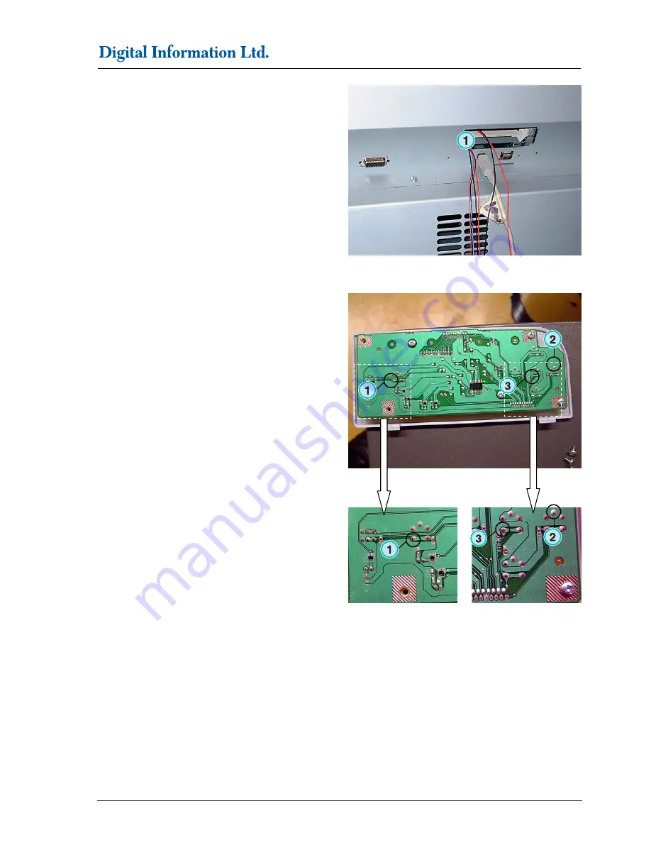
Feed the keypad and motor cables through the
Optional board opening.
(1)
Optional board opening
35.)
Turn the keypad upside down and remove the grey
metal cover. Solder the 3 wires to the respective
positions.
(1)
Red for Pause
(2)
Blue for Ground
(3)
Black for Enter
Note
Before soldering, check the wires with the layout
shown in step 41.
36.)
Feed the cable down so that it does not interfere with
the motor and the motor belt.
1
1
1
1
1
1
1


