background image

109

<

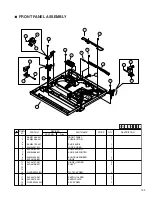
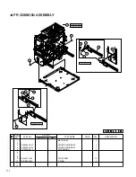
 FRONT PANEL ASSEMBLY

1

KKM11036-001

FRONT PANEL

1

2

KKM34086-001

PUSH BUTTON

1

3
4

KKM34139-001

SLIDE KNOB

1

5

KJM34087-001

LOCK SLIDER

1

6

KJS46162-001

COMP. SPRING

1

7

KJM34088-001

SLIDE SUPPORTER

1

8
9

KJM34090-001

SHOCK ABSORBER

2

10

KJP46156-B01

HINGE

2

11

KJP46157-A01

HINGE HOLDER

2

12

KJD46158-001

SHAFT

2

13
14
15

QYSDSF3008N

TH. TAP SCREW

9

16
17

KJP46274-A01

EARTH HOLDER

1

18

KJP46275-001

EARTH PLATE

1

19

QYSPSPL2004N

ASY SCREW

2

20

SYMBOL

NO.

PRICE

PART NO.

PART NAME

QTY

DESCRIPTION

REVISED

PART NO.

Rev.

1

2

4

5

7

6

9

9

10

11

12

15

15

15

15

15

10

11

12

18

17

19

Summary of Contents for EDI secure XID580i

Page 1: ... in magnetic encoder CX21ICL Series Large type IC unit Power supply Fed from the printer 5V 5 DC 12V 5 DC 24V 5 DC Current dissipation 500mA 300mA 1A Mass 3 5kg Dimension mm 110 W 221 D 255 H Accessories Joint plate 1 Inter unit cable 1 CX21ICS Series Small type IC unit Power supply Fed from the printer Mass 0 5kg Dimension mm 50 W 152 D 115 H Accessories Screw with washer 3 Screw without washer 2...

Page 2: ...OWER SUPPLY UNIT 22 2 12 REMOVAL OF SENSORS AND SWITCHES 23 2 12 1 Removal of the Cam Sensor 23 2 12 2 Removal of the Card Outlet Sensor 23 2 12 3 Removal of the Ink Encoder Circuit Board 23 2 12 4 Removal of the External Unit Power Circuit Board 23 2 12 5 Removal of the Turnover Initial Position sensor 24 2 12 6 Removal of the Card Near empty Sensor 24 2 12 7 Removal of the No Card Sensor 24 2 12...

Page 3: ...or the Time of Exchange of the CPU Circuit Board 65 MG ENCODING UNIT 66 1 MG Encoding Specifications 66 1 1 Magnetic Encoder Specifications 66 1 2 General Equipment Specifications 66 2 Block Diagram 67 2 1 MG Unit Block Diagram 67 2 2 Connection Diagram 68 3 MG Encoding Unit Exchange Method 69 3 1 Repair Classification 69 3 2 Exchange Method 69 3 3 DIP Switch Specifications 71 3 4 MG related Error...

Page 4: ...e specified for compli ance with recognized codes pertaining to X ray emission Consequently when servicing these products replace the cath ode ray tubes and other parts with only the specified parts Under no circumstances attempt to modify these circuits Unauthorized modification can increase the high voltage value and cause X ray emission from the cathode ray tube 12 Crimp type wire connector In ...

Page 5: ...ible parts RF terminals antenna terminals video and audio input and output terminals microphone jacks earphone jacks etc Measuring Method Power ON Insert load Z between earth ground power cord plug prongs and externally exposed accessible parts Use an AC voltmeter to measure across both terminals of load Z See figure 9 and following table 2 5 Grounding Class 1 model only Confirm specified or lower...

Page 6: ...the model name are used to differentiate between destinations and specifications Model name XID580i MODEL NAME 1 Detailed specifications Portion Internal option Nil No option Standard model B Equipped with ISO magnetic encorder IC contact ...

Page 7: ...screw and then raise the cover to remove it Pass the cable through the notch Screw with washer provided Screw provided 2 Connect the connector Please note that the connector has directionality 3 Install the unit with three screws Install the screws so that the cable of the connector is not caught 4 Install the cover with two screws ...

Page 8: ...all the magnetic unit Fix with three black screws 8 at the front and four black screws 8 at the rear 5 Install the bracket fixing the MG circuit board with four screws 6 Pass the wires of power switch Explanation drawing 1 CN12 11 KWR17110 001 9 x6 8 8 8 12 KWR18416 001 TSA0141 2 1 TFA0023 G NO 004 6 J9 J10 14 KWS0767 002 KWS0768 001 J14 J10 J14 J10 15 13 KWS0744 001 J14 J10 CN3 Clamp Explanation ...

Page 9: ...ly upwards 2 Insert the optional card tray diagonally downwards Note The cleaning roller should be left as it is 3 Enter the service mode of the printer main unit select Card Loading under the maintenance items and switch from standard to Right Side 4 Settings other than this and operating procedures are dependent to the user system Note If there are 10 cards accumulated continuously in the card t...

Page 10: ...t U11 FPGA U12 SDRAM 64Mbit U1 DAConverter LCD module 16columX2line SWX6 COLOR LED LEDX2 BUZZER U17 USB chip X1 XTAL 48MHz U7 STEP MOTOR DRIVER Q2 Q3 TRANSISTOR Q5 TRANSISTOR Q6 TRANSISTOR Q7 TRANSISTOR U8 STEP MOTOR DRIVER U11 STEP MOTOR DRIVER U13 DC MOTOR DRIVER U14 DC MOTOR DRIVER U15 DC MOTOR DRIVER SOLENOID PLATEN ROLLER SOLENOID IC CONTACT OPTION FAN THERMAL HEAD FAN CARD FAN PRINTER CARD M...

Page 11: ...RIVE PWB POWER SUPPLY UNIT N AC IN L AC IN SSR2N SSR2L SSR1N SSR1L CN3 VTH CN1 5V 12V CN2 24V CN8 24V_RC CN4 CONTROL SIGNAL N AC OUT L AC OUT to ANALOG POWER PWB FAIL SIGNAL to DRIVE PWB HEATER PROTECTOR PWB POWER SWITCH CN1 CN2 AC VOLTAGE DETECT PHOTO COUPLER ABNORMAL CURRENT DETECT PHOTO COUPLER Primary Secondary SSR1L SSR2L ON OFF CN5 SSR CN7 CN6 SSR ...

Page 12: ...WB 24V_RC POWER SUPPLY UNIT DRIVE PWB Cassette SW PWB Door SW PWB J16 J18 J7 J6 CN8 Door SW PWB OPEN and Cassette SW PWB OPEN 24V OFF Cleaning roller SW PWB OPEN Card Tray SW PWB OPEN Turn Motor STOP Card Motor STOP Pick up Motor STOP Pick up Motor STOP Specification of Interlock Switch CN3 Vth CN1 5V 12V CN2 24V CN4 24V_RC Vth_RC MAIN PWB ...

Page 13: ...I F BLOCK 32bit CPU BUS 16bit Data CPU Flash Memory AD CONVERTER CONTROL BLOCK SDRAM I F BLOCK HEATER CONTROL BLOCK The Heaters are controlled by each temperature PRINT BLOCK Temperature correction Outline emphasis LUT MOTOR CONTROL BLOCK INTERNAL CLOCK GENERATOR Microcode Memory 1 512Word x 16bit Data Processor Sensor input Motor Solenoid Control Signals Retransfer Heater Control Signal Bend Reme...

Page 14: ...film supply motor Remedial Heat Roller Thermistor Card outlet sencer Retransfer Heat Roller Thermistor Cam sensor Retransfer Heatroller Positionning sensor Card tray interlock Thermal Head Cleanning roller interlock Door interlock Cassette interlock Ink start position sensor Cooling fan AC AC Cooling fan POWER SWITCH Remedial Heat roller Retransfer Heat roller Thermostat DC24V DC5 12V 24V Step Mot...

Page 15: ...rd sensor circuit board Turnover initial position sensor Card supply sensor No card Ink FG sensor encorder circuit board Retransfer film mark sensor circuit board Card outlet sensor Bend remedial roller sensor Cam sensor Card near empty sensor Platen roller Bend remedial roller Retransfer roller Thermal head Turnover unit NG card outlet roller Card supply roller ...

Page 16: ... 4 Solenoid Card pick up motor Ink take up motor Ink supply Motor Turn over motor Turn over feed motor Retransfer film supply motor Retransfer film take up motor Cam motor Card feed motor Platen Solenoid Rear veiw ...

Page 17: ...Circuit Boards Power Supply Unit and Fans Door interlock switch Card tray interlock switch Cassette interlock switch Cleanning roller interlock switch MAIN PWB Drive PWB Power supply unit Heater protector PWB Front PWB ...

Page 18: ...13 Ventilation fan Thermal head cooling fan Ventilation fan Card cooling fan ...

Page 19: ...14 7 RF ID RF ID unit ...

Page 20: ...ng down use the screw B for provisional fixing so that the MG circuit board does not move 1 1 REMOVE THE TOP COVER AND THE REAR PANEL 1 Remove the filters on both sides of the top cover Caution If they are not removed the filters will be damaged when the top cover is moved 2 Remove the seven screws A and pull the top cover to the rear to remove it 3 Remove the screw B and take off the rear panel S...

Page 21: ... pulling it slowly to the front 2 REMOVAL AND EXCHANGE OF THE MAIN PARTS 2 1 REMOVAL OF THE HEAT ROLLER CAUTION Immediately after the power has been switched OFF the retransfer roller and the bend remedial roller are still hot Please perform the work after these rollers have cooled down sufficiently as otherwise burns may be caused 1 Refer to section 2 2 and remove the cam motor 2 Remove each roll...

Page 22: ...for the lower screw If the power supply unit is in the way raise it once and use the gap underneath to perform the work 2 Remove the screw B from front side Refer to section 2 9 to remove the front panel 3 Insert the screwdriver to the hole fixing the card cool ing fan and remove another screw B Refer to section 2 14 3 4 Disconnect the flat wire and the other cables 5 Raise the bend remedial rolle...

Page 23: ...ard by pulling it in diagonal direction 9 10 14 13 Stepping motor SA 17 18 Gear setting method Slit 6 7 QYSPSPD3006Nx2 Double gear 12 Before installing the gear install it on the bracket Engage with the cam gear 20 Cam gear P4 Cam motor QYREE4000X 20 Install so that the slit of the cam gear comes to the gear edge of the double gear when seen from above Please use care as the installation orientati...

Page 24: ...usted 2 After assembly has been performed leave the screw tightened provisionally 3 Turn the motor all the way in arrow direction and tighten the screw securely 4 When installing the motor assembly the tension ad justment of another belt is required 5 Install the two screws 6 Tighten the four screws provisionally 7 Hook the tension spring 8 Tighten the four screws securely 9 Install the bobbin hol...

Page 25: ...eave the screw 8 tightened provisionally 3 Turn the motor all the way in arrow direction and tighten the screw 8 securely 4 Engage the belt and tighten the screw provision ally 5 Apply the tensioning spring 6 Securely tighten the screws which have been tight ened provisionally Ink take up motor Ink supply motor DPSP4008Nx2 P5 18 D1 D2 20 3 Tighten provisionally Set the springs to tighten the belt ...

Page 26: ...age Remove the spring as one of the screws is hidden by the spring 2 8 REMOVAL OF THE CARD PICKUP MOTOR 1 The card pickup motor assembly can be removed after the two screws have been removed 2 9 REMOVAL OF THE FRONT PANEL 1 Remove the retransfer film and the ink ribbon cas sette 2 Remove the card tray 3 Remove the cleaning unit 4 When the six screws 4 and the screw 5 for earth wire have been remov...

Page 27: ... damage the disk of ink encoder located above when securing the screw 2 11 REMOVAL OF THE POWER SUPPLY UNIT 1 Disconnect the wires and the connectors 2 Remove the two screws 0 3 When ordering a power supply unit also order the wire clamps around it at the same time Explanation drawing 1 Explanation drawing 1 Engage the bearing with the rear frame 11 19 QYSPSPD4008Nx2 TSS0179 12 Plunger 17 QYSPSPD ...

Page 28: ...oder Circuit Board Function The ink feed quantity is decided by the pulses of this encoder Start position is decided by the ink start posi tion sensor 1 The bracket can be removed after the two screws have been removed 2 12 4 Removal of the External Unit Power Circuit Board Function When a small external IC unit is connected power is supplied from this power supply The thermistor detecting the env...

Page 29: ... checks whether there are remaining cards or not An error is caused when the remaining quantity becomes zero 1 Refer to section 2 7 and remove the turnover and card feed motor 2 The sensor can be removed after the screw has been removed 2 12 8 Removal of the Retransfer roller Remedial Roller Sensor Function This sensor detects the origin of the retransfer roller and the bend remedial roller Energi...

Page 30: ...bracket holding the sensor can be re moved when the screw has been removed 2 12 10 Removal of the C L Interlock Circuit Board and the Card Supply Sensor Function C L interlock switch This sensor detects the presence or absence of the cleaning unit When the switch is OFF no power is supplied to the driver IC for the card supply motor and the turnover motor Card supply sensor This sensor checks whet...

Page 31: ...r the screw 15 has been removed 2 12 12 Removal of the Cassette Interlock Circuit Board Function This circuit board detects the presence or absence of the retransfer film and the ink ribbon cassette The DC 24 V power put out from the power supply unit is cut off when the door interlock switch and the cas sette interlock switch are not both ON 1 Refer to section 2 10 and remove the platen sole noid...

Page 32: ...lling the oil bearing and the E ring 3 Turn the turnover unit by hand and check that the wire does not get caught 2 12 14 Removal of the Turnover Card Sensor Circuit Board Function This sensor checks for correct card storage at the time of card supply and card turning 1 Refer to section 2 9 and remove the front panel 2 Turn the turn unit so that the sensor circuit board comes to the top 3 The sens...

Page 33: ... 14 3 Removal of the Card Cooling Fan 1 Refer to section 2 9 and remove the front panel 2 The card cooling fan can be removed after the two screws 6 have been removed Suction fan 14 QYSPSPD 3012Nx2 2 Pass the fan wire through the notch Clamp the wire of suction fan Thermal head cooling fan Red Insert the red wire first so that the wires will be arranged nicely after connector insertion Loosen the ...

Page 34: ... the Ventilaion Fan 1 Remove the rear panel and the junction connector 2 Remove the two screws for the fan Rear Panel SA Rear Panel SA Remove the clump Remove the junction connctor QYSDSP 4008N 11 F3 F3 QYSPSPD3030N X2 12 ...

Page 35: ...A 14 15 25 QYREE5000X 22 QYYASPW4004F 21 011 x1 5 A side with the stage A side with the stage Tension the belt and tighten the screw securely Belt setting x2 17 At the time of installing the main roller SA also engage the front belt x3 6 13 Belt setting Tension the belt and tighten the screw securely M116 50S2M192 20 16 KJJ46271 003 x2 10 4 17 QYYASPW4004F 6 7 REE5000 11 Engage the bearing with th...

Page 36: ...oved Be careful not to damage the platen roller other wise print quality may be affected 3 After assembling remove the protection sheet 13 16 QYREE5000X 14 9 3 QYSPSPD 4008N x2 1 2 9 PLATEN ARM SA R PLATEN ARM SA F 007 A B C C PLATEN ARM SA F Platen roller With protection sheet 7 5 003 8 10 QYREE7000X 010 QYSPSPD4008N 3 20 A 7 6 PLATEN ARM SA R 003 long short 15 14 007 17 18 QYYASPW3004F Projected...

Page 37: ...rews 0 are removed and the cir cuit boards are pulled out Caution at the time of exchange of the Main circuit board 1 Values set in user mode and service mode are stored on the Main circuit board Accordingly when the cir cuit board has been replaced by a new one these set values must be stored For details refer to Service Mode Parameter Push and Pop 2 The connectors tend to break in performing rem...

Page 38: ...he head exchange cover of the enclosure The head exchange cover can be removed by re moving the screw and sliding the cover to the rear Notes 1 When the connector at the time of installation is inserted with the pins not correctly aligned the connector will be damaged Please insert it after aligning it correctly 2 When the heater element on the thermal head is hit at the time of exchange it can be...

Page 39: ...t results those owned by the user Every step corre sponds to a displacement of about 0 17 mm The step can be varied in the range between 15 and 15 2 Press ENTER to save the setting 3 Print and check the result 4 To adjust to the standard setting In the service mode print color patterns on single sides of 4 to 5 sheets Adjust so that the distance from the card edge to the box enclosing the line A i...

Page 40: ...ER Setting of the printing density Standard Density Low Density High Density User s LUT Select with and save with ENTER Card cooling fan ON OFF On Off Select with and save with ENTER Different type of JIS magnetic encoding Lo Co Hi Co Select with and save with ENTER Card supplying direction Standard Right Side Select with and save with ENTER Test pattern setting Step Vth Registration Addres Color ...

Page 41: ... to the initial indication In case of an error the buzzer sounds and the LED lights When there is no error the indication just returns to the initial indication In case of an error the buzzer sounds and the LED lights When there is no error the indication just returns to the initial indication ADPORT0 C277 FCFC ENTER EXIT Value obtained by A D conversion of the thermistor value of the heater or he...

Page 42: ...g the 1152 head heater elements 1 Determines the displacement amount according to the print results those owned by the user Every step corresponds to a displacement of about 0 17 mm The step can be varied in the range between 15 and 15 2 Press ENTER to save the setting 3 Print and check the result 4 To adjust to the standard setting In the service mode print color patterns on single sides of 4 to ...

Page 43: ...sor so that the ink sensor defect the ink color yellow and magenta as trans mission and cyan and Bk as interruption Select thresh old value by using and buttons and press the EN TER button to save the select Value Select User s LUT when the print density similar to that of CX710 is needed 2 2 3 Offset Trf X Setting 1 Determine the displacement amount according to the print results those owned by t...

Page 44: ...is used to confirm that the power supply volt age compensation Vth has been done correctly same density 3 Registration This is used to confirm that each color overlaps cor rectly 4 Address The head has 1152 heater elements This is used to confirm the uniformity of the density for each heater element 5 Color This is a pattern for overall evaluation 6 Black For checking of black ink blurring drop ou...

Page 45: ... motoriscut itwillnotoperate andinspectionshouldbeperformed 1 Ink TUP Mo ink take up motor Remove the inkribbon cassette When OK is displayed press the ENTER but ton to perform take up operation 2 Ink SPY Mo ink supply motor Remove the inkribbon cassette When OK is displayed press the ENTER but ton to perform supply operation 3 Media TUP Mo retransfer film take up motor Remove the retransfer film ...

Page 46: ...serial No and the head supply voltage Vth are displayed And the total lighting time of the heaters retransfer and bend remedy can be displayed And it is possible to clear the total lighting time to zero after replacing those heat ers 2 6 Parameter Push and Pop This printer has two EEPROMs for storage of data for the thermal head and for user and service mode When the Main PWB is exchanged the sett...

Page 47: ... 3 The cam motor is returned to the initial position 4 The card feed motor is run to discharge any intermediate cards 5 Ink ribbon and retransfer film are positioned to the start position Error stop is performed in case of an abnormality OPERATION OF THE MECHANISM Printing task Ink task Transport task Printing Retransfer Positioning to the start Rewinding Retransfer 1 Card supply Printing Printing...

Page 48: ...ard feed motor also operates at the same time At this time the cleaning roller and the roller in the turnover unit also rotates and the card is stored in the turnover unit Period 4 The turnover unit turns once from the card supply position to the printing position Period 5 The card is fed from the turnover unit to the card edge sensor Period 6 The card feed to the retransfer standby po sition and ...

Page 49: ...card sensor Card supply sensor Turnover card feed motor Cleaning roller Card pickup motor Card supply roller Card edge sensor Card feed motor Turnover unit printing position NG card outlet roller Card supply roller ...

Page 50: ...riod 2 The retransfer film take up motor runs to take up film slack Period 3 The platen is pushed against the thermal head Then thermal head is energized and print ing is start Period 4 Delay time for separation of ink ribbon and film Period 5 After printing the ink ribbon and the film stick to each other and during this period the ink take up motor operates to separate them Notes The printing pos...

Page 51: ...46 Retransfer film supply motor Retransfer film take up motor Platen roller Thermal head Ink supply motor Ink take up motor Ink ribbon Thermal head Platen roller Retransfer film ...

Page 52: ...otor operates and the bend re medial roller is moved to the standby posi tion Period 5 The user mode has the item Cooling time setting and during this period the opera tion is stopped for the set time of 1 to 15 seconds There is no card feed roller between the retransfer roller and the bend remedial roller Card movement in this interval is done sticking to the film Period 6 The film is moved to th...

Page 53: ...lm supply motor Retransfer film take up motor Platen roller Retransfer film mark sensor Card edge sensor Card feed motor Cam motor Card outlet sensor FRONT VIEW CAM MODE INITIAL MODE RETRANSFER MODE BEND REMEDIAL MODE ...

Page 54: ... CW CCW OFF CW CCW Rep OFF Fix Hi Lo N1 1 2 3 4 5 Card feed motor Retransfer film supply motor Retransfer film take up motor Cam motor Retransfer film mark sensor Period 1 The cam is returned to the intial position Period 2 In the same way as for the preceding item a card cooling period exists Period 3 The card is fed in the direction towards the turnover unit to separate card and film and peeling...

Page 55: ...rd edge sensor Turnover motor Turnover intial position sensor OFF CCW CW Hi Lo 1 2 Period 1 The turnover motor operates to the position sensor detection Period 2 The turnover motor is reversed and the po sition of turnover unit is fine adjusted Period 1 The card feed motor and the turnover card feed motor operate and the card is fed Period 2 The turnover motor operates and the turno ver unit is tu...

Page 56: ...Ink supply Ink take up Bend remedial roller Cartridge shaft Cartridge shaft Film mark sensor Ink start position sensor Platen Retransfer roller Head H H H L L H H L L L K C M Y Y K Ink ribbon transport direction End mark 2 5cm Ink start position sensor Ink FG sensor In case of positioning the ink ribbon to the start position The boundary between magenta and cyan is detected by the sensor for the i...

Page 57: ...ct operation of intermediate gears 7 When this message appears at the time of power ON the sensor is broken Use the sensor check of service mode for confirmation 8 Check for contamination of the cleaning roller Clean the roller if it is dirty The life of the cleaning roller is about one year The adhesive power gets lost with use for many years It is also possible that the roller becomes worn and n...

Page 58: ...ct operation of the card cooling fan rotates only at the time of retransfer If the card sticks to the film replace the film by a different film and try printing 2 Check the condition of the rubber on the retransfer roller surface 3 Perform the diagnostic test in service mode and check the operation of the card feed motor Check belts gears etc 1 When this message appears at the time of power ON the...

Page 59: ...ette and confirm the ink installation condition Confirm that there is no winding deviation or similar to prevent error of the sensor In case of winding deviation check the shaft the bobbin holder etc of the ink cassette 6 If winding eleviation is serious then replace the ink ribbon with a new one 1 Perform the diagnostic test in service mode and confirm the operation of the turn over motor 2 When ...

Page 60: ...r protector circuit board 3 Heat roller unit Defective thermistor etc This is a defect of the heater control system 1 Analog power circuit board Defect of the circuit performing A D conversion for the thermistor 2 Heater protector circuit board 3 Retranser roller unit Defective thermistor etc Thermistor Measure with a tester about 220 kΩ at normal temperature and about 1 kΩ at 200 C 4 Measure the ...

Page 61: ...g fan operate normally Perform cleaning 3 In case of reoccurrence the thermal head is defective Exchange the head 1 When the head EEPROM is defective 2 When the EEPROM on the CPU circuit board is defective Exchange parts Heater protector circuit board Heat roller unit Main circuit board Heater protector circuit board Heat roller unit Heat roller unit Power supply unit Heat roller unit Main circuit...

Page 62: ...m if the operation of the card edge sensor and the film sensor is normal and if these sensors are firmly se cured 2 When sensors are replaced setting Offset Trf X for the film sensor and or setting Offset Card X for the card edge sensor shall be adjusted Large card bend in case of single sided printing in case of double sided printing Heat deformation occurs easily especially with PVC cards 1 The ...

Page 63: ... drive pully on the retransfer film supply motor Defective registration Some part is not trans ferred correctly remains on the film side 1 The card is dirty 2 The use environment temperature is low 3 The card material is not suitable 1 Check that the card surface has not been touched with bare hands 2 Use the unit at a higher use environment temperature 3 Raise the temperature setting for the retr...

Page 64: ...y become blurred or may be missing some parts In such a case increase the character size or use bold characters In case of using small characters due to print image de sign refer to page 30 of the instruction manual 2 When the head or the platen roller is worn out due to long time use characters may be printed with some parts miss ing In that case replace with a new head or platen roller The print...

Page 65: ...notable with thin background colors the ink ribbon is not being wound uniformly Check the ink take up motor and the mechanism Check for smooth rotation of the bobbin holder of the ink cassette 1 When this is notable with normal printing the ink cas sette has not been inserted completely Confirm that it has been inserted until a cassette button locks ...

Page 66: ...AIN PWB are output to their target PWBs For details see the overallblockdiagram 5V 12V 24V Vth H T Protector MAIN MAIN MAIN MAIN DRIVE DRIVE DRIVE FRONT FRONT Source Device Power Supply Unit Power Supply Unit Power Supply Unit Power Supply Unit Target PWB Usage 5V Logic IC Analog IC Amp Comp etc Actuator Thermal Head 5V TOP 24V Vth 3 3V 1 9V 2 5V 5VREF 3 3VREF CPU CPU CPU CPU USB IF MAIN MAIN DRIV...

Page 67: ... head Use a cleaning card 8 Bobbin inner Clean with the vacuum cleaner etc 9 Shaft of Ink Cassette Film Cassette Alcohol Use anhydrous alcohol 10 Bearings of each rotating part and around them Clean with a vacuum cleaner or wipe with a dry cloth 11 Card housing of hopper and around it Clean with a vacuum cleaner or wipe with a dry cloth 12 Interior of hopper Clean with a vacuum cleaner or wipe wit...

Page 68: ... card pick up motor test in service mode Smooth rotation at the time of start Smooth rotation at the time of start Smooth rotation at the time of start Smooth rotation at the time of start The life is about 180 000 screens The life is about 120 000 screens The life is about 200 000 cards No Item Inspection contents Inspection standard Work contents Remarks 5 Roller related Check the card supply fe...

Page 69: ...n Sometimes Always At the time of film exchange before after Unknown Sometimes Always At the time of film exchange before after First time in the morning Unknown Sometimes Always At the time of film exchange before after Unknown Sometimes Always At the time of film exchange before after First time in the morning Unknown Provide more details in regard to the conditions at the time of occurrence 1 L...

Page 70: ...it board The service repair circuit board has been adjusted before shipping 3 Caution Items for the Time of Exchange of the Main Circuit Board 1 When the main circuit board is exchanged the user mode and service mode settings must be stored on the new circuit board For details refer to the item 2 6 Parameters Push Pop of service mode 2 For the other circuit boards and units there is only exchange ...

Page 71: ... in JIS X6301 6302 Coercivity Lo co 515 x 102 A m 650 Oe low coercive force Recording density 210 bpi 10 Recording method F2F modulation specified in JIS X6302 Card dimensions 85 6 mm x 54 0 mm x 0 76 mm 3 IC encoder specifications Suitable cards IC cards with external terminals as specified in ISO 7816 Contact specifications 8 contacts corresponding to ISO 7816 specifications 1 2 General Equipmen...

Page 72: ...C Card Encode PWB I F Contact Serial Port User Option MG MAIN PWB 5V Error Micro SW for Test E PWB F PWB LED Solenoid Drive Solenoid MG Write Encode sensor CPU H8 3039F B PWB C PWB DC Power Main PWB SW1 SW2 SW3 Main PWB MG Encode Curcuit CN1 J4 J5 J3 J7 J6 Only producton line use CN9 Drive PWB CN10 CN8 CN11 CN12 CN6 CN5 CN7 JIS ...

Page 73: ...CN13 J C B I E ICC02 CN5 CN6 CN7 CONTACT IC ENCODER PWB OPTION J7 A MG MAIN PWB Relay PWB Head I F PWB KWH4139 10 Contact PWB ISO MG Head IC Contact Solenoide Sensor PWB Sensor PWB Sensor PWB 75 Encode Sensor 210 Encode Sensor Stepping Motor Card Sensor Head Sensor Head Sensor Head Sensor PRINTER UNIT CN9 CN12 CN11 CN8 CN10 ...

Page 74: ... of track position may happen In that case confirm of each value and re adjust in the following steps 3 MG Encoding Unit Exchange Method 3 1 Repair Classification For the repair of MG encoding unit send back the whole printeri ncludeing the MG encoding unit to the factory 3 2 Exchange Method For each MG unit the track position TRK the IC contact position IC and the MG write start position STX are ...

Page 75: ...on a 5 66mm or less b 8 46 8 97mm c 8 46 8 97mm d 11 76 12 27mm e 12 01 12 52mm f 15 32 15 82mm measure at the center holizontal direction 1st track magnetic stripe a b c Card edge Specification a 6 3mm or less b 6 0mm or more c 11 7mm or more ISO Track Position JIS Track Position measure at the center holizontal direction CONTACT LABEL PART NO KXL46372 001 5 Confirm IC contact position in the fol...

Page 76: ...on Minus direction IC card stop position adjustment No 6 ON ON OFF OFF ON ON OFF OFF Adjustment value mm 0 0 2 0 4 0 6 0 8 1 1 2 1 4 IC card stop position adjustment IC contact position No 1 ON OFF ON OFF ON OFF ON OFF No 3 ON ON ON ON OFF OFF OFF OFF No 4 ON OFF Adjustment direction Plus direction Minus direction STX position adjustment No 2 ON ON OFF OFF ON ON OFF OFF Adjustment value mm 0 0 25 ...

Page 77: ...e MG card for scratches Card Scratches are caused for new cards MG head 3 Is the flexible wire deformed 4 Check the DIP switch settings on the MG main circuit board 5 Defective MG main circuit board 6 Life of the MG head On the side of the printer 1 Check the setting direction of the MG cards 2 Confirm the Hico and Loco settings 3 Defective drive circuit board 4 Confirm the operation of the card f...

Page 78: ...ed Remove the me chanical unit for solenoid exchange 1 4 Removal of the IC Main Circuit Board 1 Remove the two screws 17 2 Disconnect the connectors from the circuit board and pull the circuit board to remove it Caution Before exchange set the DIP switches SW1 and SW2 according to the circuit board setting 1 5 Others For removal of other parts refer to the Parts table QYSDSP3006Nx5 3 3 QYSDSP4008N...

Page 79: ...ontact SERIAL1 Card DC24V Sensor Card Position LED User Option 5V Error PWB PWB DC24V SW1 IC Card Encode PWB Contact or Contactless SW2 Antenna CPU H8 3039F Antenna Contact DC Power Serial I F SERIAL2 DC12V DC5V IC MAIN PWB CN7 CN11 CN12 CN6 CN13 CN1 CN3 CN8 CN4 CN9 CN5 CN10 ...

Page 80: ... chip 2 Use the service mode Offline Test to test the external IC unit Repeat the test 2 or 3 times so that contact scratches can be observed easily No 1 2 3 4 5 6 7 8 Specifications Fixed to ON IC card stop position adjustment SW1 No 6 ON OFF ON OFF ON OFF ON OFF No 7 ON ON OFF OFF ON ON OFF OFF No 8 ON ON ON ON OFF OFF OFF OFF Adjustment value mm 0 0 18 0 36 0 54 0 72 0 90 1 08 1 26 Contact IC c...

Page 81: ...he personal Lit Blinking Blinking Blinking Not lit Disconnection 24V line Switch setting error Jam error Communication error with the printer IC encoding error Treatment 1 Is the printer I F cable connected correctly 2 Defective IC main circuit board 3 Is 24V output by the printer 1 Are the DIP switch settings on the IC main circuit board correct 2 Defective IC main circuit board 1 Is card feed pe...

Page 82: ...T GND GND DC24V DC24V TxD STATUS nMODE DC12V DC5V GND DC24V Type I I I O O I Spec Receive Data Control Signal for CPU Reset Send Data 0V Control Signal for CPU Printer I F Connector CN1 Pin 1 2 3 4 5 6 7 8 9 10 Short GND CTL VCC GND RST VPP CLK I O Name GND Card set Signal 5V supply voltage Signal ground Reset Supply Voltage Clock Data RFU RFU Chip card C1 C2 C6 C3 C7 C4 C8 IC Encode PWB I F Conne...

Page 83: ...ntain safety We do not supply any parts that are not listed or show a in the parts column This price may be changed to reflect fluctuations in the market price There is a label on the rear panel of the printer which lists the version of the mechanism and power supply When placing an order for a part be sure to check the version before ordering to avoid any possible incompatibilities For example in...

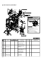
Page 84: ...RING 4 17 KJY44486 002 OIL BEARING 2 18 0081 STRIKE2 1 19 KXC44641 001 CAUTION LABEL 1 20 SYMBOL NO PART NO PART NAME PRICE QTY DESCRIPTION REVISED PART NO Rev CARD CASE SA 6 7 5 6 Approx 35 mm Hang it on TOK BEARING after hooking the both end 12 15 8 9 14 12 10 4 PICK UP SA CARD CASE SA 13 Screw thread on the tip Long side Hook to case 18 About 0 2 mm from the top 19 Explanation drawing 1 PICK UP...

Page 85: ... B01 SEPARATOR PLATE 1 7 KJM45489 B02 SEPARATOR 1 8 9 10 KJJ46271 004 ASY SCREW 1 11 QYSDSP3006N SCREW 1 12 13 14 SYMBOL NO PART NO REVISED PART NO Rev PART NAME PRICE QTY DESCRIPTION 6 7 10 11 0 76 0 25 Explanation drawing 1 7 PICK UP BASE ...

Page 86: ...124 A01 CASSETTE BUTTON 1 4 5 KJM33124 A02 CASSETTE BUTTON 1 6 7 KJS33103 002 TENSION SPRING 2 8 9 10 YMC 05 H 0 MINI CLAMP 1 11 QYREE5000X E RING 2 12 13 14 15 16 17 18 SYMBOL NO PART NO PRICE PART NAME QTY DESCRIPTION REVISED PART NO Rev 11 3 11 7 7 5 1 10 ...

Page 87: ...22 KWS0764 002 WIRE ASY 1 23 24 CX220 FAN2 FAN MOTOR 1 Card cooling fan 25 26 27 KJP33142 B01 FAN BKT 1 28 29 KJZ45597 A02 BRUSH 1 30 SYMBOL NO PART NO REVISED PART NO Rev PRICE PART NAME QTY DESCRIPTION HEAD RAIL SA 13 Sticking 8 INK FRAME SA 13 Sticking 13 Sticking 7 DUCT FRAME SA Explanation drawing 1 2 3 1 x2 Match four corners with the hole on the BKT 15 CENTER FRAME SA 5 6 14 18 19 20 TPS024...

Page 88: ...same level Explanation drawing 9 FRONT SENSOR SA 6 6 6 6 DUCT FRAME SA Explanation drawing 1 2 MEDIA FRAME 6 HEAD RAIL SA INK FRAME SA 1 6 F1 6 6 Take out the cable from a front side and clamp it 5 Note that the half punch does not get on BKT when you fix the BKT by screw Refer to front page for Explanation drawing 1 to 7 CENTER FRAME SA F1 Pass the wire through the notch in the bracket 1 3 GUIDE ...

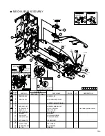
Page 89: ...5 KJY44486 002 OIL BEARING 4 26 KJP46406 B01 TOP SUPPORT BKT 1 27 QYREE3000X E RING 1 28 QYREE4000X E RING 3 29 QYREE5000X E RING 6 30 QYSPSPD3008N ASY SCREW 1 31 KJJ46271 003 TAP SCREW 13 33 GB TS 1 GREASE 1 34 KJP46352 A01 GASKET HOLDER 2 35 KJY46337 003 GASKET 2 SYMBOL NO PRICE PART NO PART NAME QTY DESCRIPTION REVISED PART NO Rev 17 16 18 19 19 ADJUST ROLLER SA Explanation drawing 2 21 25 22 2...

Page 90: ...ard near empty sensor 6 7 Bearing can be seen Apply the grease onto shaft of No 12 double gear by one grain of rice 3 15 Clamp 1 2 19 1 20 2 Apply the grease onto three shafts by one grain of rice 18 Apply the grease onto cog each gear fully until it comes to look yellow 4 Clamp 17 19 17 Clamp 4 19 12 13 Card near empty sensor Card presence sensor 11 11 Film mark sensor Head cooling fan Turn senso...

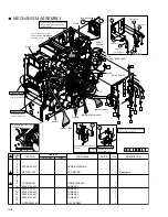
Page 91: ...side 13 1 13 13 L FRAME SA REAR PLATE SA FRONT PLATE SA 13 13 13 Clamp F1 Pass the wire inside a shaft Clamp Match the projection on the shaft and the attachment hole on the frame Clamp Fixing positions of shaft and sensor Fix the side to rear frame by screw 12 side 10 8 14 14 Pass the wire of edge sensor under the INK BKT 2 Explanation drawing 1 L FRAME SA 3 13 5 KWR 10303 010 4 6 6 Sticking Stic...

Page 92: ...1 GASKET 1 19 KJY46337 002 GASKET 4 SYMBOL NO PRICE PART NO PART NAME QTY DESCRIPTION REVISED PART NO Rev 16 16 KJJ46271 003x2 5 5 6 6 18 QYREE4000X 14 QYREE4000X 7 7 KJJ46271 003x2 10 10 14 19 19 19 19 Affix NG CARDPULLEY SA 1 2 QYREE5000X 15 QYREE5000X 15 Enlarged Enlarged Enlarged Gasket sticking position Explanation drawing 2 ROLLER COVER SA 12 9 KJJ46271 003 16 Explanation drawing 2 Explanati...

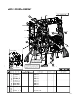
Page 93: ...N ROLLER 1 14 KJY32775 007 BEARING 2 B F8 146 15 KJJ46364 001 WASHER 1 16 QYREE5000X E RING 2 17 KJD46363 A01 STOPPER RING 1 18 QYYASPW3003F W SET SCREW 1 19 20 KJP45561 B01 PLATEN SH LEVER 1 SYMBOL NO PRICE PART NO PART NAME QTY DESCRIPTION REVISED PART NO Rev 16 14 9 3 1 2 9 PLATEN ARM SA R Explanation drawing 2 Explanation drawing 1 PLATEN ARM SA F 007 A C C Explanation drawing 1 PLATEN ARM SA ...

Page 94: ...OR ASSEMBLY 1 CX220 PIM1 PICK UP MOTOR 1 Card pick up motor 2 3 4 5 6 7 8 9 KJP45480 A01 PICK UP MO BKT 1 10 QYSPSPD2604N ASY SCREW 3 11 12 SYMBOL NO PRICE PART NO PART NAME QTY DESCRIPTION REVISED PART NO Rev 1 10 9 ...

Page 95: ...D MOTOR BKT 1 16 QYSPSPD3006N ASY SCREW 2 17 18 HL 18 0 HARNESS LIFTER 1 SYMBOL NO PRICE PART NO PART NAME QTY DESCRIPTION REVISED PART NO Rev Tap hole Explanation drawing 1 MOTOR SA Put the pulling out hole to the motor side 4 1 5 Tap hole Tighten provisionally A B Tighten the screw B securely to turn the motor in arrow direction to tighten the belt and then tighten the screw A securely Explanati...

Page 96: ...EMBLY 1 CX220 MWM1 MEDIA W MOTOR 1 Retransfer film take up motor 2 3 4 5 6 7 8 9 KJP45497 B01 DC MOTOR BKT 1 10 QYSPSPD2604N ASY SCREW 3 11 12 SYMBOL NO PRICE PART NO PART NAME QTY DESCRIPTION REVISED PART NO Rev 10 9 1 D3 ...

Page 97: ...2771 045 TIMING BELT 1 80S2M224 Width 8mm 16 17 SYMBOL NO PRICE PART NO PART NAME QTY DESCRIPTION REVISED PART NO Rev 5 7 11 12 10 12 11 8 14 13 QYSBST3006Nx2 S2M224 S2M224 F689ZZ F689ZZ Explanation drawing 1 1 4 Tap hole Explanation drawing 1 MOTOR SA MOTOR SA Put the pulling out hole to the motor side Note the direction Draw in the direction of the arrow and install Tighten provisionally Tighten...

Page 98: ...07 BEARING 1 8 9 KJD45503 001 M SUPPLY SHAFT 1 10 11 QYSPSPD4008N ASY SCREW 1 12 QYWBS438505N P L WASHER 1 13 PHD 14 HOLDER 1 14 15 SYMBOL NO PRICE PART NO PART NAME QTY DESCRIPTION REVISED PART NO Rev 2 1 7 6 9 13 11 5 Tighten provisionally Tighten by specified torque 2 16 N m 22 kgf cm Loosen this screw enough Bring the bracket on the motor side to free 12 ...

Page 99: ... 2 CX220 INW1 INK W MOTOR 1 Ink take up motor 3 4 5 6 7 8 KJP33102 B01 DC MOTOR BKT2 1 9 QYSPSPD2604N ASY SCREW 6 10 KGES 14 SPACER 1 11 LWS 3S 2W LOCKING WIRE SA 1 12 SYMBOL NO PRICE PART NO PART NAME QTY DESCRIPTION REVISED PART NO Rev 1 10 9 9 8 11 D2 D1 D1 D2 D2 D1 2 ...

Page 100: ...v Apply grease to a small gear by one grain of rice 1 9 10 14 13 17 18 Install so that the slit of the cam gear comes to the gear edge of the double gear when seen from above Slit 6 7 DOUBLE GEAR Please use care as the installation orientation can be mistaken easily Apply a sufficient quantity of grease to the two holes for the shaft 12 Before installing the gear install it on the bracket Engage w...

Page 101: ...QYSPSP3006N ASY SCREW 4 8 9 KJM45505 001 GEAR 1 10 KJM45506 001 DOUBLE GEAR 1 11 12 KJS45482 004 COMP SPRING 1 13 14 QYREE3000X E RING 2 15 16 17 YMC 05 H 0 MINI CLAMP 1 18 LWS 5S 2W LOCKING WIRE SA 1 19 SYMBOL NO PRICE PART NO PART NAME QTY DESCRIPTION REVISED PART NO Rev Top Under 14 14 10 9 7 7 6 Explanation drawing 1 Explanation drawing 1 12 18 1 2 17 P2 P1 P1 P2 ...

Page 102: ...SY 1 SYMBOL NO PRICE PART NO PART NAME QTY DESCRIPTION REVISED PART NO Rev PRESS ROLLER SA 15 16 8 15 9 8 1 Explanation drawing 1 5 5 11 19 7 12 12 21 QYSBST 3006Nx2 4 6 x2 Hook side Spring side Attach each rail so that a hook side is turned up and a spring side is turned down Explanation drawing 2 Sensor SA Explanation drawing 2 Sensor SA 002 002 16 Install this so that it may be passed under the...

Page 103: ...00X E RING 2 16 Q03093 836 SPACER 1 SYMBOL NO PRICE PART NO PART NAME QTY DESCRIPTION REVISED PART NO Rev Explanation drawing 1 8 7 14 15 13 002 2 Pass the wire underneath the sumi tube Connect the connector Pay attention to the wire passing direction 6 5 x2 Install the gear holding it so that it will not drop down 12 002 15 NG CARD ROLLER Install so that the bracket of the turn unit goes under th...

Page 104: ... QYREE5000X E RING 8 SYMBOL NO PRICE PART NO PART NAME QTY DESCRIPTION REVISED PART NO Rev Explanation drawing 3 MAIN ROLLER SA 15 15 3 3 1 AL ROLLER SA 1 2 15 15 12 12 Explanation drawing 2 002 002 Explanation drawing 5 Same on the rear AL ROLLER SA 12 15 002 5 Explanation drawing 1 CARD OUT ROLLER SA x2 7 Explanation drawing 4 Explanation drawing 7 Explanation drawing 3 8 MAIN ROLLER SA Explanat...

Page 105: ... 22 QYYASPW4004F W SET SCREW 8 23 24 25 QYREE5000X E RING 3 26 27 28 SYMBOL NO PRICE PART NO PART NAME QTY DESCRIPTION REVISED PART NO Rev 11 22 9 20 x4 x3 30S2M118 25 5 1 21 011 x4 MAIN ROLLER SA Explanation drawing 1 4 19 22 012 30S2M132 30S2M266 7 8 10 011 At the time of installing the main roller SA also engage the front belt Please insert from the front Explanation drawing 2 ANTI BEND ROLLER ...

Page 106: ...KJJ46271 003 TAP SCREW 3 17 QYYASPW4004F W SET SCREW 2 18 19 QYREE4000X E RING 1 20 QYREE5000X E RING 2 21 SYMBOL NO PRICE PART NO PART NAME QTY DESCRIPTION REVISED PART NO Rev Tension the belt and tighten the screw securely 30S2M116 50S2M192 3 20 16 10 4 17 6 7 JOG DIAL SA Engage the bearing with the frame pull it to the front and fix it with an E ring 11 Explanation drawing 1 Explanation drawing...

Page 107: ...solenoid bracket Explanation drawing 3 KWS0747 001 Door interlock TPS0248 001 E Cassette interlock 9 8 Explanation drawing 2 Explanation drawing 2 Lead the wire along the bracket so that it does not become an obstacle on the inside of the bracket 1 Explanation drawing 1 16 6 15 Engage the bearing with the rear frame 3 2 010 TSS0183 11 17 TSS0179 12 Plunger 17 Door interlock Clamp 16 Clamp Explanat...

Page 108: ...0X E RING 1 27 KJM46479 001 ENCODER DISK 1 28 TPS0248 001 M INK ENCODER PWB 1 ink encoder pwb 29 KWS0757 001 WIRE ASY 1 30 GB TS 1 GREASE SYMBOL NO PRICE PART NO PART NAME QTY DESCRIPTION REVISED PART NO Rev 11 18 KWS0751 002 9 Explanation drawing 1 6 EXT POWER PWB S3 18 Retransfer roller position sensor Remedy roller position sensor 18 18 13 13 Card discharge sensor Cam sensor 10 KWS 0757 002 18 ...

Page 109: ... Insert the shaft of gear Tighten provisionally Engage and tension the belt then tighten the screw securely Set the belt to the pulley 19 Tighten provisionally P1 P2 KWS0668 002 Clamp Clamp Fix the wire by screw as drawing 8 Secure the two screws 1 1 1 4 Hook the both ends of the spring Check that he shaded parts of the two brackets are in parallel 3 Loosely secure the three screws 5 1 3 2 Media s...

Page 110: ...etransfer heat roller Clamp the wires of thermistor and thermostat Clamp the wires of thermistor Pass the wires behind the lever Apply grease to the hole of the heater lever especially to the gray part about the size of a grain of rice Insert the lever of remedy heater to between the sensors Insert the lever of retransfer heat roller to between the sensors Position of heater lever HEATER SENSOR SA...

Page 111: ...n the INK S W MOTOR and plate of motor Before installing the drive PWB check that the wire 3 sets passed through EDGE SADDLE Installing the spring of pulley for NG card Explanation drawing 2 16 QYSDSP3030Rx2 5 J7 KWS0757 002 KWS0751 002 DOOR INTERLOCK SA F1 D4 P4 P5 P1 P2 P3 D3 J6 J5 J11 CN201 DRIVE PWB SA TRAY INTERLOCK FRONT SENSOR P4 P1 F1 F3 D4 D3 J7 J6 J11 P2 P5 P3 D1 D2 F2 J5 F2 CLAMP CLAMP ...

Page 112: ... the wire of head through the snap bush then clamp it Head wire treatment Explanation drawing 1 8 KWS0756 001 7 6 1 KWS0685 001 KWS0743 002 KWS0742 002 3 KWR18412 001 KWR18430 001 4 J2 J1 J3 J4 J8 KWS0769 001 11 9 CLAMP CLAMP CLAMP CLAMP TURN OVER FEED MOTOR CLAMP 14 CLAMP CLAMP Only the J8 cable shall be inserted between the J3 and J4 cable The spiral tube shall fully cover the area where wires a...

Page 113: ...FILTER ASY 1 As 1 set including 3kinds 4 sheets of filters 12 13 14 QYSPSPD3012N ASY SCREW 2 15 SYMBOL NO PRICE PART NO PART NAME QTY DESCRIPTION REVISED PART NO Rev 1 14 10 11 8 7 2 Clamp the wire of suction fan R Insert the red wire first so that the wires will be arranged nicely after connector insertion Pass the fan wire through the notch Loosen the two screws of the duct frame for joint tight...

Page 114: ...LIDE SUPPORTER 1 8 9 KJM34090 001 SHOCK ABSORBER 2 10 KJP46156 B01 HINGE 2 11 KJP46157 A01 HINGE HOLDER 2 12 KJD46158 001 SHAFT 2 13 14 15 QYSDSF3008N TH TAP SCREW 9 16 17 KJP46274 A01 EARTH HOLDER 1 18 KJP46275 001 EARTH PLATE 1 19 QYSPSPL2004N ASY SCREW 2 20 SYMBOL NO PRICE PART NO PART NAME QTY DESCRIPTION REVISED PART NO Rev 1 2 4 5 7 6 9 9 10 11 12 15 15 15 15 15 10 11 12 18 17 19 ...
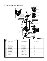
Page 115: ...M34089 002 WINDOW 1 6 7 8 QYSDSF3008N TH TAP SCREW 8 9 10 SYMBOL NO PRICE PART NO PART NAME QTY DESCRIPTION REVISED PART NO Rev 8 8 DOOR SA 2 1 5 DOOR SA Explanation drawing 1 Explanation drawing 1 Explanation drawing 2 Explanation drawing 2 Check opening and closing operation after an assembly ...

Page 116: ...EW 4 9 10 11 12 KJJ46271 003 TAP SCREW 1 13 14 SYMBOL NO PRICE PART NO PART NAME QTY DESCRIPTION REVISED PART NO Rev POWER SW SA 3 KWS0626 001 WHITE BLACK BLUE POWER SW SA 2 1 Explanation drawing 1 Explanation drawing 1 Wiring after installing the power SW onto bracket Pass the cable under the bent part of the botton bracket Pass the wire as shown in the figure x4 7 8 6 12 ...

Page 117: ... KJY44486 014 OIL BEARING 4 6 7 8 9 KJJ46271 003 TAP SCREW 10 10 QYREE4000X E RING 4 11 12 SYMBOL NO PRICE PART NO PART NAME QTY DESCRIPTION REVISED PART NO Rev 10 10 5 5 4 9 9 10 10 5 5 3 9 1 9 Installing the hopper guide Explanation drawing 1 Explanation drawing 2 Explanation drawing 2 Explanation drawing 1 ...

Page 118: ... NO PRICE PART NO PART NAME QTY DESCRIPTION REVISED PART NO Rev MAIN PWB ASY 1 TPS0242 2 11 About 3mm PWB Parts side 12 J13 J8 J12 J16 10 8 9 7 KWR15106 001 KWR15107 001 KWR15208 001 MAIN PWB ASY J22 J11 J18 J24 J23 J2 J5 J17 J15 J21 J24 J23 J22 J18 J11 Explanation drawing Explanation drawing KWS0745 001 Pass the cables J11 J18 and J22 under the cables J23 and J24 Affix the tape from the surface o...

Page 119: ... 8 10 Affix 16 16 T1 T2 J4 J3 F2 D3 P3 F1 About 30mm 17 J23 J24 16 J8 J13 Clamp the cables making the cable T1 positioned at the front Clamp the cables J3 J4 and F1 together with the cables F2 D3 and P3 Pass the cable T2 outside the other cables not clamping around here Clamp the cables T1 and T2 together making them positioned at the front Make the cables J8 and J13 routed away from the outer hop...

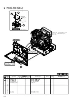
Page 120: ...KJP46797 001 USB OPTION BKT 1 12 TPS0254 001 USB CONN PWB ASY 1 13 KWS0784 001 WIRE ASY 1 14 QYSDSP3006N SCREW 1 15 QYSPSP3006N SCREW 1 16 KJJ46271 003 TAP SCREW 4 4 17 18 SYMBOL NO PRICE PART NO PART NAME QTY DESCRIPTION REVISED PART NO Rev XID580i XID580i B 7 247 1 6 KWS0666 001 8 16 CN1 4 2 2 3 1 3 USB PWB SA XID580i XID580i B 15 12 11 14 USB PWB SA 13 KWS0784 001 TPS0254 QYSDSP 3006N QYSDSP 30...

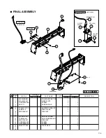
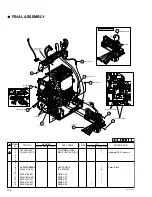
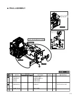
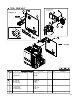
Page 121: ...44 001 WIRE ASY 1 14 KWS0767 002 WIRE ASY 1 15 KWS0768 001 WIRE ASY 1 SYMBOL NO PRICE PART NO PART NAME QTY XID580i XID580i B DESCRIPTION REVISED PART NO Rev T0137 2 12 J9 J10 J14 J10 J14 J10 CN3 FINAL ASSEMBLY CN12 CLUMP 11 KWS0785 001 9 8 QYSPSPD 3006Mx3 8 QYSPSPD3006Mx2 QYSPSPD3006Mx2 Pass the wires of power switch 8 12 KWR18416 001 CLUMPx2 TSA0141 2 1 TFA0023 14 KWS0767 002 KWS0768 001 15 13 K...

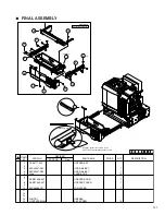
Page 122: ...BB0007 001 RF ID UNIT 1 2 KJU46660 A01 RFID COVER M 1 3 4 KWR17606 001 WIRE ASY 1 5 6 EDS 3 EDGE SADDLE 1 7 QYSPSPD3006N ASY SCREW 3 SYMBOL NO PART NO PART NAME QTY DESCRIPTION REVISED PART NO Rev T0164 3 12 Explanation drawing 1 Explanation drawing 1 CLAMP FINAL ASSEMBLY PRICE ...

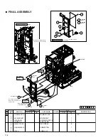
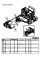
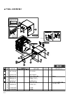
Page 123: ...D580i B FINAL ASSEMBLY KJJ46271 001x4 MG PWB SA Explanation drawing 1 4 1 6 244 1 6 10 3 245 1 2 G NO 004 G NO 002 5 6 6 KJJ46271 003 6 J1 KJJ46271 003 KJJ46271 003 J1 KJJ46271 003 6 J7 J3 J5 J4 J8 橙 3pin CN1 USB Explanation drawing 1 MG PWB SA Explanation drawing 2 Explanation drawing 2 Wiring CLAMP CLAMP CLAMP Explanation drawing 2 Clamp the USB wire with the wire from the encorder Be careful no...

Page 124: ... SYMBOL NO PRICE PART NO PART NAME QTY DESCRIPTION REVISED PART NO Rev POWER SUPPLY SA 3 3 2 4 1 100V 120V 220V 240V model Pull up the cable coming from the power switch to reduce the slack H1 10 H2 CN8 CN4 CN5 CN6 CN7 CN8 CN4 CN2 CN1 CN3 H1 H2 H1 Retransfer Heater H2 Bend Remedy Heater 7 KWS0639 001 POWER SUPPLY SA F3 H1 H2 Explanation drwing 1 Explanation drwing 2 Explanation drwing 1 Explanatio...

Page 125: ...TION REVISED PART NO Rev 4 FRONT PANEL SA TPS0219 2 3 Explanation drawing 1 Explanation drawing 1 FRONT PANEL SA Note that neither dust nor garbage are placed Hit two claws on the rear of the front panel lightly to engage it into the frame Remove the protection sheet 1 11 Be careful not to damage connectors when connecting Pass the cables coming from the front panel together with the fan wires thr...

Page 126: ...039 001 HOPPER COVER 1 9 10 KJP46284 001 JOG LEVER 1 11 12 13 14 GB TS 1 GREASE 15 QYSPSPD3006N ASY SCREW 12 SYMBOL NO PRICE PART NO PART NAME QTY DESCRIPTION REVISED PART NO Rev HOPPER SA 8 8 15 15 1 TSS0177 15 5 x6 x6 15 5 15 3 4 7 10 HOPPER SA Explanation drawing 1 Explanation drawing 1 Apply the grease the volume of one pieve of sesame uniformly on the surface ...

Page 127: ... CASSETTE ASY 1 5 6 TFS0134 001 MEDIA CASSETTE ASY 1 7 8 TFS0116 002 CLEANING ROLLER ASY 1 9 10 11 QYSPSP4008N SCREW 1 12 13 14 15 16 17 18 SYMBOL NO PRICE PART NO PART NAME QTY DESCRIPTION REVISED PART NO Rev 6 TFS0134 MEDIA CASSETTE 4 TFS0133 1 11 INK CASSETTE TFS0116 8 ...

Page 128: ... KJY46337 001 GASKET 1 8 KJY46337 003 GASKET 1 9 10 11 QYSDSP4008N SCREW 1 12 KJJ46271 003 TAP SCREW 2 13 QYSPSPD3030N SCREW 2 14 15 16 SYMBOL NO PRICE PART NO PART NAME QTY DESCRIPTION REVISED PART NO Rev FAN BKT SA 6 13 2 8 11 REAR PANEL SA F3 F3 FAN BKT SA TSS0239 AB 12 12 1 REAR PANEL SA 7 Affix Affix ...

Page 129: ... PART NO PART NAME QTY DESCRIPTION REVISED PART NO Rev FILTER R SA FILTER L SA 6 7 15 15 14 14 14 R COVER SA FILTER R SA FILTER L SA 10 9 11 10 Explannation drawing 2 FINAL ASSEMBLY Explannation drawing 2 Explannation drawing 1 Explannation drawing 1 Explannation drawing 3 Sheet edges shall be on the same level as the edges of the rectangular window 1 4 x2 R COVER SA 5 Affix the label with its win...

Page 130: ...AT T230 INSTRUCTION MANUAL 1 1 9 10 KD41811 006 POLY BAG 2 3 11 KD41811 011 POLY BAG 2 2 12 KD41811 012 POLY BAG 1 1 13 KWS0623 001 WIRE ASY 1 14 SYMBOL NO PRICE PART NO PART NAME QTY DESCRIPTION REVISED PART NO Rev XID580i XID580i B 5 Cleaning card Card stocker 006 10 6 012 12 Instructions Instruction Manual 8 006 1 10 011 A p p r o x 2 2 c m Check part number S 11 2 3 KWS0623 001 13 006 10 ...

Page 131: ... CA CAUTION LABEL 1 7 NO 3800A TAPE 1 8 9 10 11 12 13 14 15 16 17 18 SYMBOL NO PRICE PART NO PART NAME QTY DESCRIPTION REVISED PART NO Rev 6 IC M G J IS IS O IC MG JIS ISO 5 7 Mark with black pen in the way same as the old CA CAUTION LABEL As a protection for shipment Affix ...

Page 132: ...MBOL NO PRICE PART NO PART NAME QTY DESCRIPTION REVISED PART NO Rev Align the notches After installing the ink cassette paste tape onto ink cassette 1 Be careful not to break or not to be caught into the door 3 Insert it between the printing side of a head and platen As a protection for shipment As a protection for shipment ...

Page 133: ...6 17 18 SYMBOL NO PART NO PART NAME QTY DESCRIPTION REVISED PART NO Rev XID580i XID580i B T0140 12 12 TFS0136 005 2 10 x2 15 H sealing on bottom 1 U P UP C X 2 1 0 J CX 21 0J 5 TFS0136 011 6 This side up UP This side up UP 3 4 3 14 Seal with tape 8 1 1 15 H sealing on top 4 2 2 2 Front mark Paste the label on front Check the model name Wide Wide Base plate 2 RT LT RB LB Fig 1 Fig 1 Fig 1 Fig 1 Fig...

Page 134: ... in magnetic encoder CX21ICL Series Large type IC unit Power supply Fed from the printer 5V 5 DC 12V 5 DC 24V 5 DC Current dissipation 500mA 300mA 1A Mass 3 5kg Dimension mm 110 W 221 D 255 H Accessories Joint plate 1 Inter unit cable 1 CX21ICS Series Small type IC unit Power supply Fed from the printer Mass 0 5kg Dimension mm 50 W 152 D 115 H Accessories Screw with washer 3 Screw without washer 2...

Reviews: