


DG-GS1512HP User Manual
18
The switch is powered by the AC 100-240 V 50/60Hz internal high-performance power
supply. It is recommended to connect the switch with a single-phase three-wire power
source with a neutral outlet, or a multifunctional computer professional source.
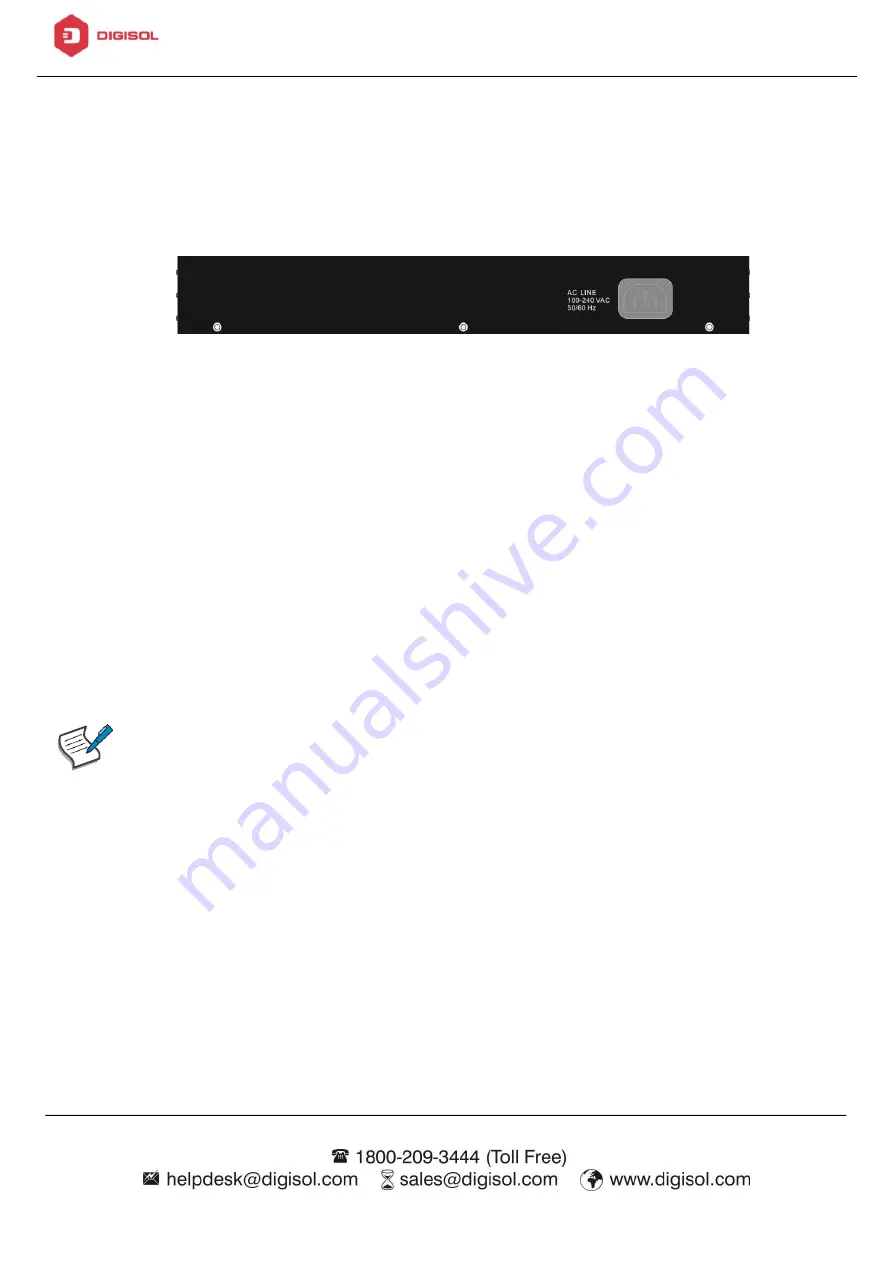
Connect the AC power connector on the back panel of the switch to the external
power source with the included power cord, and check the power LED is on.
Figure 7 - Rear View AC Power Socket
3.1.2.
Connecting to the Network
To connect the switch to the network:
1.
Connect an Ethernet cable to the Ethernet port of a computer
2.
Connect the other end of the Ethernet cable to one of the numbered Ethernet
ports of the switch. The LED of the port lights if the device connected is
active.
3.
Repeat Step 1 and Step 2 for each device to connect to the switch.
We strongly recommend using CAT-5E or better cable to connect network
devices. When connecting network devices, do not exceed the maximum
cabling distance of 100 meters (328 feet). It can take up to one minute
for attached devices or the LAN to be operational after it is connected.
This is normal behavior.
Connect the switch to end nodes using a standard Cat 5/5e Ethernet cable
(UTP/STP) to connect the switch to end nodes as shown in the illustration below.
Switch ports will automatically adjust to the characteristics (MDI/MDI-X, speed,
duplex) of the device to which the switch is connected.