background image

DigiRack Plug-ins Guide

112

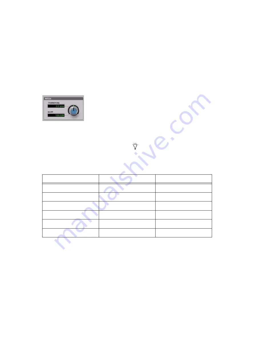
Pitch

The Pitch section provides controls for pitch 
shifting the selected audio. Use the Pitch control 
to transpose the pitch from –24.00 semitones 
(–2 octaves) to +24.00 semitones (+2 octaves), 
with fine resolution in cents.

Transpose 

Displays the transposition amount in 

semitones. You can transpose pitch from –24.00 
semitones (–2 octaves) to +24.00 semitones (+2 
octaves), with fine resolution in cents. Adjust 
the Pitch control or click the Transpose field and 
type the desired value.

Shift 

Displays the pitch shift amount as a per-

centage. You can pitch shift from 25.00% (–2 oc-
taves) to +400.00% (+2 octaves). Adjust the 
Pitch control or click the Shift field and type the 
desired value. The default value is 100% (no 
pitch shift).

Post Production Pull Up and Pull 
Down Tasks

Table 8 on page 112 provides information on 
TCE settings for common post-production tasks. 
Type the corresponding TCE% (represented to 
10 decimal places in Table 8) in the Time Shift 
field for the corresponding post-production task 
and the process the selected audio.

Time Shift plug-in, Pitch section

Use the corresponding Time Shift Plug-in 
Setting for the desired post-production task.

Table 8. Most commonly used TCE settings in Post workflows

Post workflow plug-in setting

TCE% (to 10 decimal places)

Frames

Pal to Film –4%.tfx

96.0%

25 to 24/30

PAL to NTSC –4.1%.tfx

95.9040959041%

25 to 23.976/29.97 

Film to PAL +4.1667%.tfx

+104.1666666667%

24/30 to 25

Film to NTSC –0.1%.tfx

99.9000999001%

24/30 to 23.976/29.97

NTSC to Pal +4.2667%.tfx

+104.2708333333%

23.976/29.97 to 25

NTSC to Film +0.1%.tfx

+100.10%

23.976/29.97 to 24/30

Summary of Contents for DigiRack

Page 1: ...DigiRack Plug ins Version 7 3 ...

Page 2: ...ack Digidesign Mbox Mbox 2 Mbox 2 Mini Mbox Pro MultiShell Pro Tools Pro Tools HD Pro Tools LE Pro Tools M Powered and RTAS are either trademarks or registered trademarks of Avid Technology Inc in the US and other countries All other trademarks contained herein are the property of their respective owners Product features specifications system requirements and availability are subject to change wit...

Page 3: ... Plug ins 5 Chapter 3 Working with Real Time Plug ins 9 Processing Power Requirements of TDM and RTAS Plug ins 9 Delay in Signal Processing 13 Plug ins as Inserts 15 Inserting Plug ins on Tracks 16 The Plug in Window 18 Clip Indicators 22 Using the Side Chain Input 22 Tempo Sync 23 Automating Plug ins 24 Instrument Plug ins 27 RTAS Plug ins on Auxiliary Input and Master Fader Tracks 27 HTDM Plug i...

Page 4: ...references 37 Using AudioSuite Plug ins 39 Chapter 5 Adjusting Plug in Controls 41 Adjusting Plug in Controls 41 Chapter 6 DigiRack Real Time TDM and RTAS Plug ins 43 EQ III 43 EQ II 57 Click 58 Dither 59 POW r Dither 61 D Verb 62 Dynamics III 64 Dynamics II 79 Mod Delay II 79 Signal Generator 81 SignalTools 82 Pitch 87 TimeAdjuster 90 Trim 92 ...

Page 5: ...e 102 Gain 103 Reverse 103 Signal Generator 103 DC Offset Removal 104 Time Compression Expansion 104 Pitch Shift 106 Time Shift 107 Chapter 8 Plug in Settings 115 Using the Librarian 115 Plug in Settings Dialog 118 DigiBase and Plug in Settings Files 119 Chapter 9 Using ReWire with Pro Tools 121 ReWire Requirements 122 Using ReWire 122 Tempo and Meter Changes 123 Looping Playback 124 Automating Re...

Page 6: ...DigiRack Plug ins Guide vi Appendix A DSP Requirements for TDM Plug ins 125 DSP Requirements 125 Appendix B DSP Delays Incurred by TDM Plug ins 129 Index 131 ...

Page 7: ...unction as track inserts are applied to audio during playback and process audio non de structively in real time TDM plug ins are de signed for use with Pro Tools HD software on Pro Tools HD systems and rely on the process ing power of Digidesign DSP cards The number and variety of TDM plug ins that you can use simultaneously in a session are lim ited only by the amount of DSP available You can inc...

Page 8: ...r than nonde structively in real time Depending on how you configure a non real time AudioSuite plug in it either creates an entirely new audio file or alters the original source audio file Audio Suite plug ins can be used on all Pro Tools systems and Avid software System Requirements To use DigiRack plug ins you need any the fol lowing A Digidesign qualified Pro Tools system running Pro Tools A D...

Page 9: ...on Study on your own using courses available online or find out how you can learn in a classroom setting at a certified Pro Tools training center Products and Developers Learn about Digidesign products download demo software or learn about our Development Partners and their plug ins applications and hardware News and Events Get the latest news from Digidesign or sign up for a Pro Tools demo To lea...

Page 10: ...DigiRack Plug ins Guide 4 ...

Page 11: ... Tools 2 Packs and other bundles included with your Digidesign system 3 Any additional plug ins Check with the man ufacturer of your plug ins for compatibility in formation and support Organizing Plug ins You can customize how plug in lists plug in menus are organized in the Insert selector and Plug in selector Use the Organize Plug in Menus By pop up menu in the Pro Tools Display Preferences page...

Page 12: ...r folder Most Digidesign Development Partner plug ins will be sorted as Digidesign when view by man ufacturer is enabled Category and Manufacturer Organizes plug ins in two levels of menus The top menus display plug ins by process category such as EQ Dy namics and Delay with individual plug ins listed in the category submenus The bottom menus display plug ins by their manufacturer such as Digidesi...

Page 13: ...plug in favorite to change you can select the plug in from the list of favor ites at the top of the plug in menu or in its plug in category manufacturer sub menu where the plug in appears in bold Default Plug ins You can set a default EQ plug in and Dynamics plug in which places them at the top of the In sert selector pop up menu on screen and first in the list of menu choices when assigning inser...

Page 14: ...DigiRack Plug ins Guide 8 ...

Page 15: ...portion of your system s total available DSP resources Since these DSP resources reside on the cards that make up your particular Pro Tools hard ware configuration the amount of DSP avail able depends entirely on the number and type of DSP cards in your system You can add more mixing and processing power to your system by installing additional DSP cards provided you have unused PCI or PCIe expansi...

Page 16: ...w much of your computer s processing power is currently being used by Pro Tools and how much is still available Improving RTAS Plug in Performance You can increase the number of RTAS plug ins your system can use concurrently by increasing the Hardware Buffer Size and CPU Usage Limit Hardware Buffer Size The Hardware Buffer Size H W Buffer Size con trols the size of the hardware cache used to han d...

Page 17: ...ocessors pop up menu select the number of available processors you want to allocate for RTAS plug in processing 3 Click OK CPU Usage Limit The CPU Usage Limit controls the percentage of CPU resources allocated to Pro Tools host pro cessing tasks such as RTAS plug in performance and screen redraws Lower CPU Usage Limit settings limit the ef fect of Pro Tools processing on other CPU inten sive tasks...

Page 18: ...cord even if the RTAS processing requirements ex ceed the selected CPU Usage Limit This can re sult in pops and clicks in the audio during play back and recording but does not stop the transport Minimize Additional I O Latency When enabled any additional latency due to suppressing RTAS errors during playback and record is minimized to 128 samples Suppressing RTAS errors re quires at least 128 samp...

Page 19: ...n page 27 Delay in Signal Processing DSP and host based processing in digital audio systems incurs signal delay of varying amounts Such delays can vary from as short as few sam ples to as long as several hundred samples de pending on the type of processing applied If you have recorded an instrument on multiple tracks using multiple microphones a drum kit for example and process the different track...

Page 20: ... ment plug in during recording MIDI and Audio Processing Plug ins Some plug ins such as Bruno and Reso process audio while allowing MIDI data to control pro cessing parameters When you record enable an Instrument or MIDI track that is controlling an Audio processing plug in the track the plug in is inserted on will go into low latency mode ef fectively making the processed audio play early To keep...

Page 21: ...a track s volume fader Real time plug ins are pre fader but post disk This means that if you record to disk with a plug in inserted on the record track you will hear the effect of the plug in but the effect will not be recorded to disk To record with a plug in effect create an Auxil iary Input insert the desired effect on the Aux iliary Input track then route the Auxiliary Input to the audio track...

Page 22: ...e View Mix Window Inserts To show inserts in the Edit window Choose View Edit Window Inserts To insert a plug in on a track Click the Insert selector on the track and se lect the plug in that you want to use Removing an Insert from a Track To remove an insert from a track Click the Insert selector and select No Insert Multi mono plug ins such as dynamics based or reverb plug ins may not function a...

Page 23: ... new insert location The duplicated plug in retains its original settings and automa tion Making Plug ins Inactive You can set plug ins as inactive in order to free up DSP resources for other plug ins and process ing When a plug in is inactive it retains its as signment position and related automation playlists However it will not pass audio and does not consume any DSP or TDM resources To toggle ...

Page 24: ... and import plug in settings Librarian Menu Recalls settings files saved in the plug in s root settings folder or in the current session s Settings folder See Using the Librar ian on page 115 Next and Previous Setting Buttons Let you select the next or previous plug in setting from the Librarian menu Plug ins Settings Select Button Accesses the Plug in Settings dialog which lists the settings file...

Page 25: ...ific channels of a multi mono plug in Each square represents a speaker channel The Master Link button must be disabled to use the Link Enable buttons See Linking and Unlinking Controls on Multi Mono Plug ins on page 21 Channel Selector Accesses a specific channel within a multichannel track for plug in control editing This menu appears only on multi mono plug ins inserted on tracks with more than ...

Page 26: ...but ton on the plug in whose controls you want to adjust using keyboard commands To open an additional Plug in window Shift click the Insert button for the additional plug in To open Plug in windows for each channel of a multi mono plug in Alt click Windows or Option click Mac the Channel selector in the Plug in window of the multi mono plug in To close all currently open Plug in windows Alt click...

Page 27: ... can also selectively link the con trols of specific channels To unlink controls on a multi mono plug in Deselect the Master Link button To access controls for a specific channel Select the channel from the Channel selector To link the controls of specific channels 1 Deselect the Master Link button if it is not al ready deselected 2 Click the Link Enable buttons for the chan nels whose controls yo...

Page 28: ...internally from the input signal However some plug ins let you switch between internal and external side chain processing With external side chain processing a plug in s detector is triggered by an external signal such as a separate reference track or audio source known as the key input A typical use for external side chain processing is to control the dynamics of one audio signal using the dynami...

Page 29: ... support and overall tempo capabili ties of plug ins such as ReWire client applica tions that utilize MIDI Beat Clock Tempo Sync provides a direct connection be tween session tempo and plug in parameters that support MIDI Beat Clock This direct con nection lets plug in parameters such as delay auto pan and other time domain effects auto matically synchronize to and follow changes in session tempo ...

Page 30: ...d control individually This lets you to build up complex automation in stages Preference Setting to Auto Enable All Plug in Parameters You can configure Pro Tools to enable all param eters for automation when you first assign a plug in insert To auto enable all parameters on newly inserted plug ins 1 Choose Setup Preferences and click the Mix ing tab 2 In the Automation section click to select the...

Page 31: ...k you can select from among these by clicking their buttons in the Inserts section of this dia log 4 Click OK to close the Plug in Automation dia log Accessing the Plug in Automation dialog You can also Control Alt Start click Win dows or Command Option Control click Mac any plug in control in the Plug in window then choose Open Automation Di alog from the pop up menu Plug in Automation button Plu...

Page 32: ...te additional automation to the track without completely erasing the previous pass by choos ing Auto Touch mode or Auto Latch mode These modes add new automation only when you actually move the control Record Safing Plug in Automation You can protect plug in automation from being overwritten by using Automation Safe mode To enable plug in safe mode 1 Open a plug in 2 Click the Safe button so that ...

Page 33: ...tputs are routed through the track that the plug in is inserted on and the plug in s aux iliary mono or stereo outputs are available in the track input pop up menu on other tracks RTAS Plug ins on Auxiliary Input and Master Fader Tracks Pro Tools HD Only In Pro Tools HD RTAS plug ins can be inserted on Auxiliary Input and Master Fader tracks or after TDM plug ins on any kind of track This also aff...

Page 34: ...annel Ordering RTAS and TDM Plug ins on an Audio Track With Pro Tools HD when RTAS and TDM plug ins are combined on an audio track the order in which they are inserted has different results RTAS Plug ins Grouped Before TDM Plug ins No additional voices will be used and no process ing latency will occur RTAS plug ins will be by passed when Record Enable or TrackInput mon itoring is enabled for that...

Page 35: ...transport HTDM Plug in Conversion to RTAS When you use Pro Tools 7 0 or higher to open a session that was last saved in a version of Pro Tools prior to 7 0 most HTDM plug ins will be automatically converted to their RTAS coun terparts However in rare cases as with some third party plug ins these plug ins will not automatically convert to RTAS and display as inactive This means that the plug in eit...

Page 36: ...DigiRack Plug ins Guide 30 ...

Page 37: ...le EQ filters Click Creates an audio click as a tempo reference for performing and recording Compressor Limiter III Processes audio with compression or limiting Chorus Processes audio with chorusing Flanger Processes audio with flanging Expander Gate III Processes audio with ex pander gating De esser III Processes audio with de essing to re move sibilance Duplicate Creates a new continuous source ...

Page 38: ...tion Reference This menu aims the selected process at either re gions selected in an audio track or playlist or at regions selected in the Audio Regions List When you select a region on screen in either a track playlist or the Region List Pro Tools nor mally selects both occurrences of the region Since you may not want to process both this menu provides a convenient means of limiting the AudioSuit...

Page 39: ...ed in other playlists those copies of the original unprocessed region will not be replaced File Mode Selector This menu lets you select whether or not the Au dioSuite plug in will process the selected audio destructively or nondestructively and how the original files will be modified There are three options Overwrite Files Processes the selected regions de structively overwriting the original audi...

Page 40: ...te plug in as well as some third party AudioSuite plug ins lets you choose whether you want to perform processing on a channel by channel track by track or an all chan nel all tracks basis using the Chan Track Process Mode selector Peak On Each Chan Track Analyzes and pro cesses each selected track individually If you ap ply the Normalize plug in to multiple tracks or a multichannel track in Peak ...

Page 41: ... is affected by the AudioSuite Buffer Size option on the Processing page of the Pro Tools Preferences dialog See AudioSuite Processing Preferences on page 37 Bypass When Bypass is enabled the selected audio is auditioned without AudioSuite processing The Bypass button applies only to previewing It does not affect actual AudioSuite processing Process Clicking this button begins AudioSuite process i...

Page 42: ...s Menus The Settings and Librarian pop up menus that appear in some AudioSuite plug ins provide a means of saving loading copying pasting and organizing custom plug in settings files See Using the Librarian on page 115 Analyze Button This button analyzes a selection without actu ally processing it On the DigiRack Gain plug in you can use the Analyze feature to determine the maximum peak level on a...

Page 43: ...ith the number of selected channels determining the type of track For example five contigu ously selected channels would be processed as a 5 0 track while seven contiguously selected channels will be processed as a 7 1 track AudioSuite Processing Preferences Before you begin using AudioSuite plug ins use the Preferences dialog Setup Preferences Processing to configure default AudioSuite op tions a...

Page 44: ... bit source files during AudioSuite processing Settings Accesses options for the currently se lected Default Dither plug in In the case of the Digidesign Dither plug in this lets you to turn noise shaping on or off Bit Depth Selects the default bit depth used by the dither function during AudioSuite process ing Bit depth can be set to 16 18 20 or 24 bit TC E The TC E section lets you choose the pl...

Page 45: ...ting Tracks for Delay or Reverb Processing Because some AudioSuite effects such as delay and reverb add additional material to the end of the selected audio it is important that you make a selection that is longer than the original source material so that the plug in can write it to the audio file If you select only the original mate rial without leaving additional space at the end any reverb deca...

Page 46: ...e Continuous File from the File Mode pop up menu 4 Click the Preview button to begin audition processing of the selected material 5 Make further adjustment to the plug in pa rameters based if necessary 6 When you are satisfied with the Preview re sults click the Process button The selected audio is processed according to the settings you have specified Pro Tools appends an acronym to the region s ...

Page 47: ...arameters Using a Mouse You can adjust rotary controls by dragging hor izontally or vertically Parameter values increase as you drag upward or to the right and decrease as you drag downward or to the left Keyboard Shortcuts For finer adjustments Control drag Win dows or Command drag Mac the control To return a control to its default value Alt click Windows or Option click Mac the con trol Editing ...

Page 48: ...lay the current value of the parameter You can edit the numeric value of a parameter using a scroll wheel To change control values using a scroll wheel 1 Click the text box corresponding to the con trol that you want to adjust 2 To increase a value scroll up with the scroll wheel To decrease a value scroll down with the scroll wheel Toggling Switches To toggle a switch Click the switch Groups and ...

Page 49: ...g con trol surfaces Digidesign D Control Digidesign ProControl Digidesign Control 24 Digidesign 002 Digidesign Command 8 Mackie HUI compatible controllers EQ III has a Frequency Graph display that shows the response curve for the current EQ settings on a two dimensional graph of frequency and gain The frequency graph display also lets you modify frequency gain and Q settings for indi vidual EQ ban...

Page 50: ... in Controls The rotary controls on the EQ III Plug in can be adjusted by dragging over them horizontally or vertically Dragging up or to the right incre ments the control Dragging down or to the left decrements the control Typing Control Values You can enter control values directly by clicking in the corresponding text box typing a value and pressing Enter Windows or Return Mac Inverting Filter G...

Page 51: ...on the control or on its corresponding text box Using Band Pass Mode You can temporarily set any EQ III control to Band Pass monitoring mode Band Pass mode cuts monitoring frequencies above and below the Frequency setting leaving a narrow band of mid range frequencies It is especially useful for adjusting limited bandwidth in order to solo and fine tune each individual filter before re verting the...

Page 52: ...annel where the plug in is being used Input Polarity Control The Input Polarity button inverts the polarity of the input signal to help compensate for phase anomalies occurring in multi microphone envi ronments or because of mis wired balanced connections Input and Output Meters 7 Band EQ and 2 4 Band EQ Only The plasma style Input and Output meters show peak signal levels before and after EQ proc...

Page 53: ...ton is light gray the band is by passed and unavailable Band Gain Control Each Peak and Shelf EQ band has a Gain control for boosting or cutting the corresponding fre quencies Gain controls are not used on High Pass Low Pass or Notch filters Frequency Control Each EQ band has a Frequency control that sets the center frequency Peak Shelf and Notch EQs or the cutoff frequency High Pass and Low Pass ...

Page 54: ...each of the enabled filters to the overall EQ curve 1 Band EQ The Frequency Graph display in the 1 Band EQ shows a control dot that indicates the center fre quency Peak Shelf and Notch Filters or the cutoff frequency High Pass and Low Pass filters for the currently selected filter type Frequency Graph display for the 7 Band EQ High Pass control dot Low Mid control dot High Mid control dot Low Pass...

Page 55: ...aneous use In the factory default setting the High Pass Low Notch and Low Pass High Notch bands are out of circuit the Low Shelf and High Shelf bands are se lected and in circuit and the Low Mid Peak Mid Peak High Mid Peak bands are in circuit 7 Band EQ and 2 4 Band EQ window High Pass Low Pass Low Shelf Peak Mid Peak High Shelf Peak Low Mid Peak High Mid Peak Input Output Level meters Frequency G...

Page 56: ...ass through High Notch EQ Attenuates a narrow band of fre quencies centered around the Frequency set ting The width of the attenuated band is deter mined by the Q setting The Low Pass and High Notch controls and their corresponding graph elements are displayed on screen in gray High Pass filter left and Low Notch EQ right High Pass Filter and Low Notch EQ control values Control Value Frequency Ran...

Page 57: ...ound the Frequency setting The width of the affected band is determined by the Q setting The Low Shelf and Low Peak Gain controls and their corresponding graph elements are dis played on screen in red Low Shelf EQ left and Low Peak EQ right Low Shelf EQ button Frequency control Band Enable button Gain control Q control Low Peak EQ button Frequency control Band Enable button Gain control Q control ...

Page 58: ... The Mid Gain control and its corresponding graph elements are displayed on screen in yel low Low Mid Peak EQ Low Mid Peak EQ control values Control Value Frequency Range 40 Hz to 1 kHz Frequency Default 200 Hz Low Mid Peak Q Range 0 1 to 10 0 Low Mid Peak Q Default 1 0 Low Mid Peak Gain Range 18 dB to 18 dB Frequency control Band Enable button Gain control Q control Mid Peak EQ Mid Peak EQ contro...

Page 59: ...requency setting The width of the affected band is determined by the Q setting The High Shelf and High Peak Gain controls and their corresponding graph elements are dis played on screen in blue High Mid Peak EQ High Mid Peak EQ control values Control Value Frequency Range 200 Hz to 18 kHz Frequency Default 2 kHz Mid Peak Q Range 0 1 to 10 0 Mid Peak Q Default 1 0 Mid Peak Gain Range 18 dB to 18 dB...

Page 60: ...ch of the five Peak bands Low Shelf Peak Low Mid Peak Mid Peak High Mid Peak and High Shelf Peak counting as one filter Each of the Band pass and Notch filters High Pass Low Notch Low Pass and High Notch counts as two filters When any combination of these filter types uses the four filter maximum on the 2 4 Band EQ the remaining bands become unavailable This is indicated by the Band Enable buttons...

Page 61: ...e pass through No gain control is available for this filter type Notch Filter The Notch Filter attenuates a narrow band of frequencies centered around the Frequency set ting No gain control is available for this EQ type The width of the attenuated band is deter mined by the Q setting 1 Band EQ window 1 Band EQ control values Control Value Frequency Range All 20 Hz to 20 kHz Frequency Default All 1...

Page 62: ...ng The Q setting determines the shape of the shelving curve Peak EQ The Peak EQ boosts or cuts a band of frequencies centered around the Frequency setting The width of the affected band is determined by the Q setting Low Pass Filter The Low Pass filter attenuates all frequencies above the cutoff frequency setting at the se lected rate 6 dB 12 dB 18 dB or 24 dB per oc tave while letting all frequen...

Page 63: ...utomation enabled status of EQ III plug in controls is indicated by the colored LED be neath each on screen knob and colored outlines around each on screen button Even if an EQ III band is bypassed for example when the filter capacity of a 2 4 Band EQ is sur passed its controls are still available for automa tion This lets you continue to update settings in a session in preparation for the next ti...

Page 64: ...k Track To use the Click plug in 1 Choose Options Click to enable the Click option or enable the Click button in the Trans port window 2 Do one of the following Choose Track Create Click Track Pro Tools creates a new Instrument track named Click with the Click plug in al ready inserted In the Edit window the click track s Track Height is set to Mini or Create new a mono Auxiliary Input track and i...

Page 65: ...ion bit depth The most common application of dithering is to use it on a master output mix as the last proces sor in the signal path when preparing a 24 bit session for CD mastering In this case you would insert the Dither plug in on a Master Fader to reduce session bit depth from 24 bits to 16 bits The inserts on a Master Fader track are always post fader The Dither plug in has user selectable bi...

Page 66: ...t Recommended for output to digital de vices that support a full 20 bit recording data path such the Sony PCM 9000 optical master ing recorder or the Alesis ADAT XT 20 Use this setting for output to analog devices if you are us ing a 20 bit audio interface such as the 882 20 I O audio interface The 20 bit setting can also be used for output to digital effects de vices that support 20 bit input and...

Page 67: ...f noise shaping each with its own characteris tics Try each noise shaping type and choose the one that adds the least amount of coloration to the audio being processed Type 1 Has the flattest frequency spectrum in the audible range of frequencies modulating and accumulating the dither noise just below the Nyquist frequency Recommended for less stereophonically complex material such as solo instrum...

Page 68: ...put level See also Clip In dicators on page 22 Input Level The Input Level slider adjusts the input volume of the reverb to prevent the possibility of clip ping and or increase the level of the processed signal Mix The Mix slider adjusts the balance between the dry signal and the effected signal giving you control over the depth of the effect This control is adjustable from 100 to 0 Algorithm This...

Page 69: ...e used to vary the range of a reverb from large to small Generally you should select an algorithm first and then choose the size that approximates the size of the acoustic space that you are trying to create Diffusion Diffusion sets the degree to which initial echo density increases over time High settings result in high initial build up of echo density Low set tings cause low initial buildup This...

Page 70: ... formats only In addition to standard controls in each mod ule Dynamics III also provides a graph to track the gain transfer curve in the Compressor Lim iter and Expander Gate plug ins and a fre quency graph to display which frequencies trig ger the De Esser and which frequencies will be gain reduced Adjusting Dynamics III Controls You can adjust Dynamics III plug in controls by clicking and dragg...

Page 71: ...eyboard editing mode Enabling Buttons To enable a button click it Using a Control Surface Dynamics III can be controlled from any sup ported control surface interface and worksur face Refer to the appropriate controller product guide for more information Shared Compressor Limiter and Expander Gate Features The following parts of the user interface are shared between the Compressor Limiter and Ex p...

Page 72: ...erent colors during dynamics processing Light Orange Indicates that gain reduction is within the knee and has not reached the full ratio of compression Dark Orange Indicates that gain reduction is be ing applied at the full ratio for example 2 1 Threshold Arrow The orange Threshold arrow next to the Input meter indicates the current threshold and can be dragged up or down to adjust the threshold W...

Page 73: ...y axis The orange vertical line represents the threshold Use this graph as a visual guideline to see how much dynamics processing you are applying The Compressor Limiter and Expander Gate plug ins also feature an animated multi color cursor in their gain transfer curve displays The gain transfer curve of the Compressor Lim iter and Expander Gate plug ins shows a mov ing ball cursor that shows the ...

Page 74: ...r compres sion The Attack control sets how quickly the compressor responds to the front of an audio signal once it crosses the selected threshold The Release control sets the amount of time that it takes for the compressor s gain to return to its original level after the input signal drops below the selected threshold To use compression most effectively the attack time should be set so that signal...

Page 75: ...ecific value by setting an absolute ceiling for the dy namic range Compressor Limiter III Controls This section describes controls for the Compres sor Limiter plug in Input Output Level Meters The Input and Output meters show peak signal levels before and after dynamics processing See Levels Section on page 65 for more informa tion Unlike scales on analog compressors metering scales on a digital d...

Page 76: ...pplies attenuation to the signal If you use fast attack times you should generally use a proportionally longer release time partic ularly with material that contains many peaks in close proximity This control ranges from 10 μs fastest attack time to 300 ms slowest attack time Release The Release control sets the length of time it takes for the Compressor Limiter to be fully de activated after the ...

Page 77: ...ight orange while gain reduction has not exceeded the knee setting and switches to dark orange when gain reduction reaches the full ratio This control ranges from 0 db hardest response to 30 db softest response Gain The Gain control lets you boost overall output gain to compensate for heavily compressed or limited signals This control ranges from 0 dB no gain boost to 40 dB loudest gain boost with...

Page 78: ...ly abrupt cutoff of a gate Expander Gate III Controls This section describes controls for the Ex pander Gate plug in Input Output Level Meters The Input and Output meters show peak signal levels before and after dynamics processing See Levels Section on page 65 for more informa tion Expander Gate Dynamics Graph Display The Dynamics Graph display lets you visually see how much expansion or gating y...

Page 79: ...t fall below the threshold As you ad just the ratio control refer to the built in graph to see how the shape of the expansion curve changes This control ranges from 1 1 no expansion to 100 1 gating Attack The Attack control sets the attack time or the rate at which gain is reduced after the input sig nal crosses the threshold Use this along with the Ratio setting to control how soft the Ex pander ...

Page 80: ...Using the Side Chain Input in Dynamics III on page 76 De Esser III The De Esser reduces sibilants and other high frequency noises that can occur in vocals voice overs and wind instruments such as flutes These sounds can cause peaks in an audio signal and lead to distortion The De Esser reduces these unwanted sounds us ing fast acting compression A Threshold con trol sets the level above which comp...

Page 81: ...This meter shows different colors during de essing Light Orange Indicates that gain reduction is be ing applied but has not reached the maximum level set by the Range control Dark Orange Indicates that gain reduction has reached the maximum level set by the Range control Frequency The Frequency control sets the frequency band in which the De Esser operates When HF Only is disabled gain is reduced ...

Page 82: ...the level of gain reduction being applied to the signal Use this graph as a visual guideline to see how much dynamics processing you are applying at different points in the frequency spectrum Using the Side Chain Input in Dynamics III Compressor Limiter and Expander Gate Only Dynamics processors typically use the detected amplitude of their input signal to trigger gain re duction This split off si...

Page 83: ...en enabled this control lets you listen to the internal or external side chain input by itself as well as monitor its levels with the Output meter This is especially useful for fine tuning the plug in s filter settings or external key input HF and LF Filter Enable Buttons The HF Filter Enable and LF Filter Enable but tons toggle the corresponding filter in or out of the side chain When this button...

Page 84: ...oc tave High Pass Filter Makes triggering of dynamics processing more sensitive to frequencies above the Frequency setting rolling off at a slope of 12 dB per octave LF Frequency Control The Frequency control sets the frequency posi tion for the Band Pass or High Pass filter and ranges from 25 Hz to 4 kHz Using an External Key Input for Side Chain Processing To use a filtered or unfiltered externa...

Page 85: ...The plug in uses the filtered input signal to trigger dynamics processing 6 To fine tune side chain triggering adjust the plug in controls Dynamics II Mod Delay II There are five different Mod Delay II plug ins capable of different maximum delay times The Short Delay provides 43 ms of delay at all sample rates The Slap Delay provides 171 ms of delay at all sample rates The Medium Delay provides 34...

Page 86: ...omatically synchronize to and follow changes in session tempo For plug ins that do not support Tempo Sync the original MIDI Beat Clock window Setup MIDI MIDI Beat Clock remains available in Pro Tools For more information see Tempo Sync on page 23 Tempo Available in some plug ins that do not support Tempo Sync Tempo selects the desired tempo in beats per minute bpm This setting is independent of Pr...

Page 87: ...nes in a variety of frequencies waveforms and amplitudes It is particularly useful for gen erating reference signals with which to calibrate Pro Tools HD interfaces such as the 96 I O or 192 I O and other elements of your studio Tempo Meter Duration and Groove controls It is not possible to exceed the maximum delay length for a particular version of Mod Delay II Consequently when adjusting any of ...

Page 88: ...t clipping RMS Generates signal at levels consistent with the RMS Root Mean Square value or the effec tive average level of the signal SignalTools DigiRack SignalTools metering plug ins provide two metering modules SurroundScope and PhaseScope The SignalTools plug ins support TDM and RTAS plug in formats at all sample rates SurroundScope Pro Tools HD Only SurroundScope is a plug in that provides s...

Page 89: ...d signal that is panned equally to all channels An irregular shape that is closer to one side of the display indicates that the channels on that side have a stronger signal A teardrop shape that points toward a single channel indicates that the signal is panned to that channel PhaseScope PhaseScope is a multichannel metering plug in that provides signal level and phase information for stereo track...

Page 90: ...ick the corresponding button in the Op tions section of the plug in window Phase Meter Display The Phase Meter indicates the phase coherency of two channels of a multi channel signal The Phase Meter is green when the channels are positively out of phase values from 0 to 1 and red when the channels are negatively out of phase values from 0 to 1 At the center or zero position the signal is a per fec...

Page 91: ...dScope With SurroundScope you can select any combination of channels for Leq A metering by clicking the channel buttons around the Surround Display Selected channels are indicated in green PhaseScope With PhaseScope you can select ei ther or both channel for Leq A metering by clicking the channel buttons in the corners of the Lissajous display Selected channels are indi cated in green Leq A Meteri...

Page 92: ...e VU Volume Unit Uses AES standards for signal level indication BBC Uses IEC IIa standards for signal level indi cation This style of metering suppresses short duration peaks that would not affect broadcast program material Reference calibration 4 dB is 18 dBFS Nordic Uses IEC Type I standards for signal level indication and provides greater resolution for readings between 10 dBu and 4 dBu Refer e...

Page 93: ...cation on the meter scale Pitch Pro Tools HD Only The Pitch plug in is designed for a variety of au dio production applications ranging from pitch correction of musical material to sound design Pitch processing uses the technique of varying sample playback rate to achieve pitch transposi tion Because changing audio sample playback rate results in the digital equivalent of vari speeding with tape t...

Page 94: ...s the number of repetitions of the delayed signal You can use it to produce effects that spiral up or down in pitch with each successive echo shifted in pitch Coarse Adjusts the pitch of a signal in semitones over a two octave range Pitch changes are indi cated both in the Semitones field and in the Mu sical Staff Relative section below this slider Us ing the 8va and 8va buttons in conjunction wit...

Page 95: ...optimize crossfade times using the Crossfade slider if necessary For audio material with sharper attack transients use shorter crossfade times For audio material with softer attack transients use longer crossfade times Minimum Pitch Sets the minimum fundamental pitch that the Pitch plug in will recognize when performing pitch transposition Use this to opti mize the Pitch plug in s performance by a...

Page 96: ...is useful for alter ing the gain of a signal by a large amount in real time For example when you are working with audio signals that are extremely low level you may want to adjust the channel gain to a rea sonable working range so that a fader is posi tioned at its optimum travel position Use the Gain control to make a wide range of gain ad justment in real time without having to perma nently proc...

Page 97: ...vert the polarity phase of one of them the signals will be of opposite polarity and cancel each other out This technique is convenient for find ing the exact delay setting for any plug in To determine the delay of a plug in by inverting its signal phase 1 Place duplicate audio regions on two different audio tracks and pan them to the center mono 2 Apply the plug in whose delay you want to calculat...

Page 98: ...channel and apply the delays necessary to each channel to match this channel However this may not always be necessary You may only really need to compensate for delays between tracks where phase coherency must be maintained as with instruments recorded with multiple microphones or stereo pairs If you are working with mono signals and the accumu lated delays are small just a few samples for ex ampl...

Page 99: ...hether the Gain toggle is set to 6 or 12 6 12 Gain toggle Switches the maximum level of attenuation between dB to 6 dB and dB to 12 dB Output Meter Indicates the output level includ ing any gain compensation added using the Gain control Mute Mutes the signal output Automation data adjusts to reflect the cur rent Gain setting When working with au tomation data from an older version of the Trim plug...

Page 100: ...DigiRack Plug ins Guide 94 ...

Page 101: ...ead 7 Band EQ and 2 4 Band EQ The 7 Band EQ and the 2 4 Band EQ have the same window and identical controls but on the 2 4 Band EQ a limited number of the seven available bands can be active at the same time 1 Band EQ The 1 Band EQ has its own window with six se lectable filter types The features of these plug ins are non real time but otherwise identical to their real time coun terparts EQ II 7 B...

Page 102: ...eatures of these plug ins are non real time but otherwise identical to their real time coun terparts Dynamics II For information on individual controls in these plug ins see Dynamics III on page 64 Compressor Limiter 3 plug in Expander Gate 3 plug in De Esser 3 plug in For information see the DigiRack Legacy Plug ins Guide ...

Page 103: ...e high frequen cies are removed from the feedback signal The range of the Low Pass Filter is 20 Hz to 19 86 kHz with a maximum value of Off which effectively means bypass Delay Sets the delay time between the original signal and the chorused signal The higher the setting the longer the delay and the wider the chorusing effect Delay is adjustable from 0 20 milliseconds LFO Rate Adjusts the rate of ...

Page 104: ...effect Mix Adjusts the balance between the effected signal and the original signal and controls the depth of the effect Mix is adjustable from 0 to 100 High Pass Filter Controls the cutoff frequency of the High Pass Filter Use this to attenuate the frequency content of the feedback signal and the frequency response of the flanging The higher the setting the more low frequencies are removed from th...

Page 105: ...signal For the feedback feature to func tion the Gain slider must be raised above its lowest setting Pan The pan sliders for each of the four taps con trol their apparent location in the stereo field Delay Sets the delay time between the original signal and the delayed signal The higher the setting the longer the delay This control is ad justable from 0 1500 milliseconds 1 5 sec onds Mix Adjusts t...

Page 106: ...uency of the Low Pass Filter Use this to attenuate the high frequency content of the feedback signal The lower the setting the more high frequen cies are removed from the feedback signal The range of the Low Pass Filter is 20 Hz to 19 86 kHz with a maximum value of Off which effectively means bypass Feedback Controls the amount of feedback ap plied from the output of the delay into its input It al...

Page 107: ...n the track as inserts The original audio file regions are merely rewritten in place to a single duplicate file The Duplicate plug in works nondestructively You cannot choose to overwrite files Delay The Delay plug in provides time delay based ef fects with up to 10 9 seconds of delay at any session sample rate You can also use it to pro duce multiple delay based effects including slap echo doubli...

Page 108: ...ue below the clipping threshold or by en tering a percentage of the clipping threshold You can normalize stereo pairs together so that two sides of a stereo signal are processed relative to each other RMS Peak Toggle Switches the calibration of normalizing between Peak or RMS modes Peak normalizes the input signal at the maximum possible level without clipping RMS normalizes the input signal at a ...

Page 109: ...ible level without clipping RMS adjusts the input signal to a level consistent with the RMS Root Mean Square value or the effective average level of the selected region Reverse The Reverse plug in replaces the audio with a re versed version of the selection Signal Generator The Signal Generator plug in produces audio test tones in a variety of frequencies waveforms and amplitudes The features of t...

Page 110: ...sing or decreasing their length without changing pitch It is especially useful in audio post production for adjusting audio to specific time or SMPTE durations for synchronization purposes Time Compression Expansion is nondestructive Source and Destination The Source fields display the length of the current selection before pro cessing in each of the listed formats All fields are always active a c...

Page 111: ...ossfade times if necessary For audio material with sharper attack transients use smaller crossfade times For audio material with softer attack transients use longer crossfade times Min Pitch Sets the minimum or lowest pitch that will be used in the plug in s calculations during the Time Compression Expansion pro cess The control has a range of 40 Hz to 1000 Hz This control should be set lower when...

Page 112: ... Use this to manually adjust crossfade length in milliseconds to optimize performance of the Pitch Shift plug in according to the type of audio material you are processing This plug in achieves pitch transposition by processing very small portions of the selected audio mate rial and very quickly crossfading between these alterations in the waveform of the audio mate rial Crossfade length affects t...

Page 113: ...s to match the reference tone to the pitch of the audio play back Adjust the Gain setting to change the rel ative volume of the reference tone It may also be helpful to toggle the Reference Pitch on and off to compare pitch 4 Select the audio material to be pitch shifted 5 Adjust the Coarse and Fine Pitch Shift con trols to match the pitch of the audio playback to the reference pitch 6 Click Proce...

Page 114: ...honic Rhythmic or Varispeed Monophonic Use for processing monophonic sounds such as a vocal melody Polyphonic Use for processing complex sounds such as a multipart musical selection Rhythmic Use for processing percussive sounds such as a mix or drum loop Varispeed Use to link time and pitch change for tape like pitch and speed change effects and post production workflows Range The Audio Range pop ...

Page 115: ... and Length of the processed signal Times are dis played in units of the timebase selected in the Units pop up menu You can click the Processed End and Length fields to type the desired values These values update automatically when adjust ing the Time control Tempo Displays the Original Tempo and Pro cessed Tempo in beats per minute bpm You can click the Original Tempo and Processed Tempo fields t...

Page 116: ...ion is only available when Polyphonic or Rhythmic is selected as the Audio Type and provides slightly different controls for each When Polyphonic is selected as the Audio Type the Transient section provides controls for set ting the transient detection threshold and for adjusting the analysis window length for pro cessing audio Time Shift plug in Formant section Audio with a fundamental pitch has ...

Page 117: ...ng drums and percussive tracks to achieve the best results Window Sets the analysis window length for pro cessing audio You can set the Window from 6 0 milliseconds to 185 0 milliseconds Adjust the Window control or click the Window field and type the desired value The Window control is only available when Polyphonic is selected as the Audio Type The default for Window size is 18 0 milliseconds an...

Page 118: ...e The default value is 100 no pitch shift Post Production Pull Up and Pull Down Tasks Table 8 on page 112 provides information on TCE settings for common post production tasks Type the corresponding TCE represented to 10 decimal places in Table 8 in the Time Shift field for the corresponding post production task and the process the selected audio Time Shift plug in Pitch section Use the correspond...

Page 119: ...the DigiRack Plug ins Guide AudioSuite TCE Plug in Preference The Time Shift plug in s high quality time com pression and expansion algorithms that can be used with the Pro Tools TCE Trim tool To select Time Shift for use with the TCE Trim tool 1 Choose Setup Preferences 2 Click the Processing tab 3 From the TC E Plug in pop up menu select Time Shift 4 Select the desired preset setting from the De...

Page 120: ... Time Shift 2 Select the Audio Mode appropriate to the type of material you are processing Monophonic Polyphonic or Rhythmic 3 In Monophonic or Polyphonic mode select the appropriate Range for the selected material Low Mid High or Wide 4 If transposing the pitch of the selection up at tenuate the Gain control as necessary 5 If using Monophonic mode adjust the For mant Shift control as desired 6 If...

Page 121: ...s Menu Use the Settings menu commands to save copy paste and manage plug in settings files Settings menu commands include Save Settings Saves the current settings This command overwrites any previous version of the settings The setting then appears in the Li brarian menu Save Settings As Saves the current settings un der a different name Copy Settings Copies the current settings You can then apply...

Page 122: ...gs are saved in the folder you specified with the Set Root Settings Folder command see below Set Root Settings Folder Selects a location or root folder for saving and importing settings This root settings folder must be named Plug in Settings Use this command only if you want to choose a location other than the default Plug in Settings folder The default location for the Root Plug in Set tings fol...

Page 123: ... destination plug in 4 Choose Paste Settings from the Settings pop up menu To create a custom User Default setting 1 Create and save a setting 2 Choose Set As User Default from the Settings pop up menu To make a plug in default to your custom setting From the Settings pop up menu choose Set tings Preferences Set Plug in Default To User Setting Creating Subfolders for Settings To make it easier to ...

Page 124: ...sing settings affects only the currently selected channel To apply an operation to all channels of an unlinked plug in Hold down the Alt key Windows or Option key Mac while performing the command Plug in Settings Dialog The Plug in Settings dialog lists the settings files for the current plug in type From this list you can select a new setting or audition a series of settings Auditioning plug in s...

Page 125: ... of seconds that will elapse between each program change and press Enter 4 Select the option for Increment Patch After the specified number of seconds Pro Tools selects the next setting 5 When you are finished auditioning settings do one of the following Click Done to stop incrementing patches and to close the Plug in Settings dialog or Select the Increment Patch option to stop incrementing patche...

Page 126: ...s Explorer or the Mac Finder to an Insert in the Mix or Edit window To change plug in settings by drag and drop Drag and drop a plug in settings file from a DigiBase browser Windows Explorer or the Mac Finder to the plug in window The plug in set tings file must be for the same plug in name For example you cannot replace a 1 Band EQ 3 with a plug in setting for 4 Band EQ 3 Searching for plug in se...

Page 127: ...nsert menus in Pro Tools Selecting a ReWire client application within Pro Tools will automatically launch that application if the client application supports this feature Any corresponding MIDI nodes for that application are available in Instrument tracks MIDI Output selector Instrument view and MIDI tracks Output selector Once the outputs of your software synthesizers and samplers are routed to P...

Page 128: ... at 96 kHz is double the load at 48 kHz You can monitor Pro Tools CPU usage in the System Usage window making sure to not overtax your system ReWire and Track Count on Pro Tools LE Systems With Pro Tools LE performance is determined by several factors including host CPU speed available memory and buffer settings Digide sign cannot guarantee 64 simultaneous audio channel outputs with ReWire on all ...

Page 129: ...ls session With the Pro Tools Conductor button selected Pro Tools always acts as the Tempo master us ing the tempo map defined in its Tempo Ruler With the Pro Tools Conductor button dese lected the ReWire client acts as the Tempo mas ter In both cases playback can be started or stopped in either application Some ReWire client applications such as Reason support a single stereo output path Reason s...

Page 130: ...cify the loop within the ReWire client application and begin playback Automating ReWire ReWire supports automation for switching in puts during playback To automate switching inputs during playback 1 Set the track s automation to write 2 Do one of the following Change the input link pop up menu man ually or Draw the automation in the Edit window If you create a playback loop by making a selection ...

Page 131: ...el HD Core and HD Process cards pro vide identical chip sets HD Accel cards provide newer more powerful DSP chips making the HD Accel card ideal for DSP intensive plug ins and for high sample rate sessions Not all plug ins are supported on all types of chips The following tables indicate the number of compatible chips per card DSP Requirements DSP requirements for DigiRack TDM plug ins are provide...

Page 132: ...P chip for Pro Tools HD cards at 44 1 and 48 kHz Plug in HD Accel HD Core and HD Process mono stereo mono stereo EQ III 1 band 66 33 28 14 EQ III 2 4 band 36 18 15 7 EQ III 7 band 23 11 10 5 Click 18 n a 3 n a Dither 46 43 34 18 D Verb 6 6 4 4 Compressor Limiter III 18 11 7 5 Expander Gate III 16 11 7 5 De Esser III 12 8 5 3 Mod Delay II short 74 36 43 21 Mod Delay II slap 73 36 32 16 Mod Delay II...

Page 133: ...l time TDM plug ins per DSP chip for a Pro Tools HD Core and HD Process card at 48 kHz Plug in LCR Quad LCRS 5 0 5 1 6 0 6 1 7 0 7 1 DSP Chips per HD Card DigiRack Pitch partial partial partial partial partial partial 9 D Verb partial partial partial partial partial partial 9 Compressor Limiter III 3 3 2 2 2 2 9 Expander Gate III 3 3 2 2 2 2 9 De Esser III Mod Delay I short 14 11 8 7 6 5 9 Mod Del...

Page 134: ... Usage The System Usage window Window System Usage shows approximately how much DSP is avail able in your system and how it is being used in the current Pro Tools session Time Adjuster medium 30 22 18 15 13 11 9 Time Adjuster long 10 8 6 5 4 4 9 Trim 39 29 23 19 16 14 9 Signal Generator 8 6 5 4 3 3 9 SurroundScope SignalTools 4 3 2 2 1 1 9 Table 2 Continued Theoretical maximum instances of real ti...

Page 135: ...nce this can cause the channels to be slightly out of phase Table 3 shows the delays inherent in each type of Digidesign TDM plug in Pro Tools HD systems provide automatic Delay Compensation to compensate for sig nal processing delays For detailed informa tion see the Pro Tools Reference Guide Table 3 Samples of delay incurred by each real time DigiRack TDM plug in on HD cards Plug in Samples of D...

Page 136: ... 4 Mod Delay II extra long 4 Dither 4 POW r Dither 4 Time Adjuster 4 Signal Generator 4 SignalTools SurroundScope 4 SignalTools PhaseScope 4 Table 3 Continued Samples of delay incurred by each real time DigiRack TDM plug in on HD cards Plug in Samples of Delay on HD Cards ...

Page 137: ... Delay 100 Pitch Shift 106 Reverse 103 Signal Generator 103 Time Compression Expansion 104 using 39 AudioSuite processing on networked hard drives 39 AudioSuite window 32 Audition pop up menu 35 Auto button 18 automation Auto Latch mode 26 Auto Touch mode 26 creating 26 plug in 24 preferences 24 Safe button 18 Automation Safe button 18 Auxiliary Inputs inserting RTAS plug ins 27 B BBC metering 86 ...

Page 138: ... 104 destination folder for plug in settings 116 Diffusion control 63 DIN metering 86 Dither 6 Dither bit depth for AudioSuite 38 Dither plug in 59 61 pop up menu 38 DSP and EQ III 54 DSP delay compensation 14 91 92 DSP delays 129 DSP delays inherent in plug ins 129 Duplicate plug in 101 duplicating inserts 17 D Verb 62 Dynamics 6 Dynamics II plug ins 64 Dynamics III 96 AudioSuite 96 E Edit Settin...

Page 139: ...5 Reset 85 Window 85 Leq A Meter 85 Level control 82 LFE Enable button 19 LFO Rate control 97 98 LFO Waveform control 97 98 LFO Width control 97 98 Librarian menu 18 Link Enable buttons 19 linking plug in controls 21 Lissajous Meter 84 Lock Settings File command 116 locked regions and AudioSuite processing 39 Long Delay plug in 79 Low Pass Filter control 64 97 M Manufacturer 6 Master Faders insert...

Page 140: ... 83 Ping Pong Delay plug in 100 pink noise 82 Pitch plug in 87 Pitch Shift 6 Pitch Shift plug in 106 Pitch transposition 87 Playlist command 32 plug in controls adjusting 64 linking 21 Plug in Controls Default to Auto Enabled 24 Plug in selector for AudioSuite plug ins 32 for real time plug ins 18 plug in settings librarian 36 115 Plug in window 18 closing multiple windows 20 opening multiple wind...

Page 141: ...16 settings 36 choosing a destination for 116 copying 117 creating subfolders 117 creating User Default 117 importing 117 pasting 117 saving 117 Settings Preferences command 116 Settings menu 18 Short Delay plug in 79 shortcuts for keyboard input 64 sibilants 74 side chain definition 22 filters 22 processing 19 Side Chain Listen 23 side chain processing 22 Signal control 82 signal delay 129 Signal...

Page 142: ...ch Shift 112 Polyphonic mode 108 post production workflow 112 Processed time 109 pull up pull down TCE percentages 112 Rhythmic mode 108 Tempo displays 109 Threshold control 111 Time section 109 Time Shift 109 timebase 109 Transient section 110 Transpose 112 Unit pop up menu 109 Varispeed mode 108 Window 111 TimeAdjuster plug in 90 using for delay compensation 13 Track selector 18 tracks affect of...

Page 143: ...City CA 94014 3886 USA Tel 650 731 6300 Fax 650 731 6399 TECHNICAL SUPPORT USA Tel 650 731 6100 Fax 650 731 6384 PRODUCT INFORMATION USA Tel 800 333 2137 INTERNATIONAL OFFICES Visit the Digidesign website for contact information www digidesign com ...

Reviews: