


Chapter 2
2-6
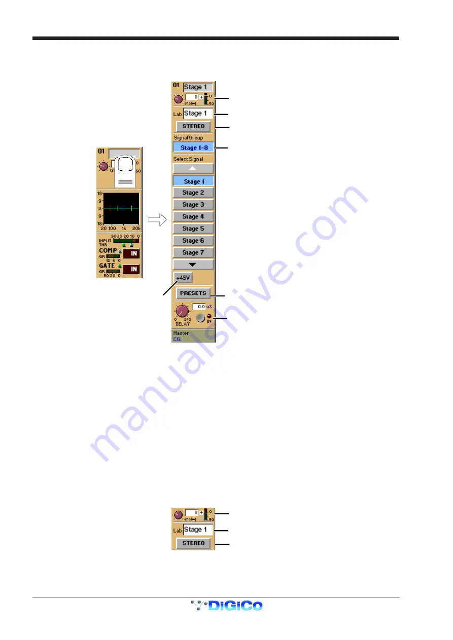
2.2.1 Input Module ........................................................................
You can display the Input Module for a fader by touching the top of the fader's on-screen channel strip, where the channel label is
displayed. You can then hide the module by touching the same area again.
Signal Group Selector
Signal Selector
Signal Label
Preset Selector
Phantom Power
(Mic i/p only)
Gain / Phase
Signal Delay
Stereo Channel Mode Selector
The Input Module contains the following controls:
Channel Label
To alter the Label, touch the Label area, then type the new label on the keyboard. Labels can be up to 31 characters long, but only the
start of the label will be displayed depending on the character width.
Signal Group
The input sockets are arranged into named "Groups". To display the signal groups, touch the Signal Group Selector area as shown
above. You can then touch the button for the group you want.
"Misc" Signal Group
The Misc group contains the console's internal signal sources and sockets, including signals from the worksurface and rear Talkback
microphones, and the internal Noise and Tone generators.
The original talkback sources (the unprocessed microphone inputs) are labelled Talk Mic L (Top) & R (Rear).
The post-processing results from the talkback input channels are labelled Talkback A & B.
Select Signal - Signal in Group
To select a source, touch the button for the signal you want to connect to the channel. If there are more than five channels in the group,
you may need to use the scroll buttons (top and bottom) to display the button for the signal you want.
Stereo Channel Mode Selector
Signal Label
Gain / Phase
Stereo Channel Mode Selector
If this button is pressed, the input channel functions will control two input signals, the one which has been selected and the next one in the
rack.
Input source, Direct output, Insert Send and Insert Return will all function as adjacent pairs so making a selection for the left signal will
result in an automatic selection for the right signal.
Summary of Contents for D5T
Page 1: ...Operation Manual Issue A September 2004 Software Versions 2 4...
Page 2: ......
Page 10: ......
Page 11: ...Chapter 1 1 1 Chapter 1 Getting Started...
Page 12: ...Chapter 1 1 2...
Page 32: ...Chapter 2 2 1 Chapter 2 Inputs and Console Channels...
Page 33: ...Chapter 2 2 2...
Page 58: ...Chapter 3 3 1 Chapter 3 Busses and Outputs...
Page 59: ...3 2 Chapter 3...
Page 68: ...4 1 Chapter 4 Chapter 4 Master Section...
Page 69: ...Chapter 4 4 2...
Page 91: ...5 1 Chapter 5 Chapter 5 The Cue List...
Page 92: ...Chapter 5 5 2...
Page 111: ...Chapter 6 6 1 Chapter 6 Automation...
Page 127: ...7 1 Chapter 7 Chapter 7 Effects...
Page 128: ...7 2 Chapter 7...
Page 135: ...8 1 Chapter 8 Chapter 8 Troubleshooting...
Page 136: ...Chapter 8 8 2...
Page 139: ...A 1 AppendixA Appendix A D5TC Theatre Masters Controller...
Page 140: ...A 2 Appendix A...
Page 147: ...B 1 Appendix B Appendix B Multiple Console Setups Inc Redundant Engines...
Page 148: ...B 2 Appendix B...
Page 162: ...B 16 Appendix B Standalone PC Screen Appearance...


