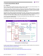
Saturn User Manual V1
Page 24
6.1.12 HDMI (J3, J4)
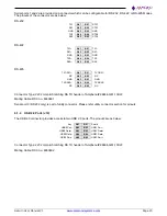
The board provides access to two HDMI ports on two identical connectors. The pinout is shown below:
Data 2+
A01
B01
GND
Data 2-
A02
B02
Data 1+
GND
A03
B03
Data 1-
Data 0+
A04
B04
GND
Data 0-
A05
B05
Clock+
Ground
A06
B06
Clock-
CEC (NC)
A07
B07
Reserved
DDC Clock
A08
B08
DDC Data
GND
A09
B09
+5V
Hot Plug Detect
A10
B10
Chassis ground
Connector Type: 2x10 2mm pitch latching RA TH header of Amphenol# 98464-G61-20ULF.
Mating cable: DSC no. 6980605
6.1.13 Analog I/O (J18)
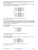
The VIO pins on the analog and digital I/O connectors are tied together on the board and provide access to jumper-
selectable 3.3V / 5V system voltage rail through a polyswitch resettable fuse. The fuse is rated for ~100mA
maximum sustained current.
Ain 0
1
2
Ain 8
Ain 1
3
4
Ain 9
Ain 2
5
6
Ain 10
Ain 3
7
8
Ain 11
Ain 4
9
10
Ain 12
Ain 5
11
12
Ain 13
Ain 6
13
14
Ain 14
Ain 7
15
16
Ain 15
Analog Ground
17
18
Analog Ground
Aout 0
19
20
Aout 1
Aout 2
21
22
Aout 3
Analog Ground
23
24
DIO C0
DIO C1
25
26
DIO C2
DIO C3
27
28
DIO C4
VIO (fused)
29
30
Digital Ground
Connector type: 2x15 contact right angle latching connector SM30B-ZPDSS-TF
Mating cable : DSC no. 6981504
6.1.14 Digital I/O (J17)
VIO (fused)
1
2
DIO A0
DIO A1
3
4
DIO A2
DIO A3
5
6
DIO A4
DIO A5
7
8
DIO A6
DIO A7
9
10
DIO B0
DIO B1
11
12
DIO B2
DIO B3
13
14
DIO B4
DIO B5
15
16
DIO B6
DIO B7
17
18
DIO C5
Ground
19
20
Ground
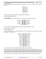
Connector type: 2x10 contact right angle latching connector SM20B-GHDS-GAN-TF.
Mating cable : DSC no. 6980501


