Saturn User Manual V1
Page 25
6.1.15 MiniCard Socket (J20)
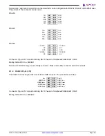
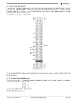
The board provides access to PCIe mini card interface via Mini card socket. For the connector shown below, all
TX/RX signals are with respect to the host. TX on the socket drives RX on the installed module, and RX on the
socket is driven by TX on the installed module. The two mounting standoffs at the far end of the module installation
site are not connected to ground. The pinout of the connector is shown below:
1
2
+3.3V
3
4
Gnd
5
6
+1.5V
Clkreq-
7
8
Gnd
9
10
PCIe 1 Clk-
11
12
PCIe 1 Clk+
13
14
Gnd
15
16
KEY
17
18
Gnd
19
20
Disable-
Gnd
21
22
PCIe Reset-
PCIe 1 RX-
23
24
+3.3V
PCIe 1 RX+
25
26
Gnd
Gnd
27
28
+1.5V
Gnd
29
30
SMB Clk
PCIe 1 TX-
31
32
SMB Data
PCIe 1 TX+
33
34
Gnd
Gnd
35
36
USB2 D-
Gnd
37
38
USB2 D+
+3.3V
39
40
Gnd
+3.3V
41
42
WWAN LED-
Ground
43
44
WLAN LED-
45
46
WPAN LED-
47
48
+1.5V
Pull-up to +3.3V
49
50
Gnd
51
52
+3.3V
Connector Type: SMT 52 position 0f 0.8mm pitch for full size mPCIE modules
Mating Cable: NA
6.1.16 FPGA JTAG (J21)
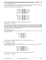
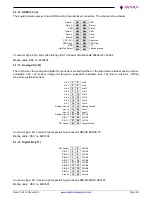
A 1x6 2mm Pin header is provided for FPGA programming at the factory and is not normally accessed by the
customer. Pinouts is shown below.
1
3.3V
2
Ground
3
TCK
4
TDO
5
TDI
6
TMS
Connector used is 1x6 2mm Vertical Header.
Mating cable: Factory test cable

