Prometheus CPU User Manual V1.44
Page 47
13. ANALOG INPUT RANGES AND RESOLUTION
13.1 Overview
Prometheus uses a 16-bit A/D converter. The full range of numerical values for a 16-bit number is
0 - 65535. However the A/D converter uses twos complement notation, so the A/D value is
interpreted as a signed integer ranging from –32768 to +32767.
The smallest change in input voltage that can be detected is 1/(2
16
), or 1/65536, of the full-scale
input range. This smallest change results in an increase or decrease of 1 in the A/D code, and so
this change is referred to as 1 LSB, or 1 Least Significant Bit.
The analog inputs on Prometheus have three configuration options:
♦
Single-ended or differential mode
♦
Unipolar or bipolar mode
♦
Input range (gain)
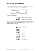
The single-ended / differential and unipolar / bipolar configuration is done with a jumper on jumper
block J13 (see page 45), and the input range selection is done in software.
13.2 Input Range Selection
Prometheus can be configured to measure both unipolar (positive only) and bipolar (positive and
negative) analog voltages. This configuration is done with a jumper and applies to all inputs. In
addition you can select a gain setting for the inputs, which causes them to be amplified before
they reach the A/D converter. The gain setting is controlled in software, so it can be changed on a
channel-by-channel basis. In general you should select the highest gain (smallest input range)
that will allow the A/D converter to read the full range of voltages over which your input signals
will vary. However, if you pick too high a gain, then the A/D converter will clip at either the high
end or low end, and you will not be able to read the full range of voltages on your input signals.
13.3 Input Range Table
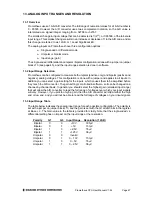
The table below indicates the analog input range for each possible configuration. The polarity is
set with a jumper on jumper block J13, and the gain is set with the G1 and G0 bits in the register
at Base + 3. The Gain value in the table is provided for clarity. Note that the single-ended vs.
differential setting has no impact on the input range or the resolution.
Polarity
G1
G0
Input Range Resolution (1 LSB)
Bipolar
0
0
±
10V 305
µ
V
Bipolar
0
1
±
5V 153
µ
V
Bipolar
1
0
±
2.5V 76
µ
V
Bipolar
1
1
±
1.25V 38
µ
V
Unipolar
0
0
Invalid
Unipolar
0
1
0 – 10V
153
µ
V
Unipolar
1
0
0 – 5V
76
µ
V
Unipolar
1
1
0 – 2.5V
38
µ
V

