Prometheus CPU User Manual V1.44
Page 16
5. JUMPER CONFIGURATION
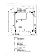
Refer to the Prometheus board drawing on page 7 for locations of the configuration items
mentioned here. Also see page 45 for information on configuration J13 for the data acquisition
circuit.
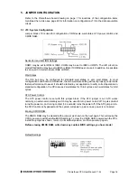
5.1 J10: System Configuration
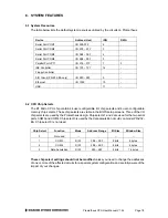
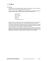
Jumper block J10 is used for configuration of IRQ levels, wait states, ATX power control, and
CMOS RAM.
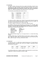
Serial Port and A/D IRQ Settings
COM3 may be set to IRQ4 or IRQ9. COM4 may be set to IRQ3 or IRQ15. The A/D circuit (on
model PR-Z32-EA) may be set to IRQ5 or IRQ4 if COM3 does not use it. In addition, it is possible
to set up all 3 circuits to share IRQ4 or IRQ5.
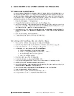
Wait States
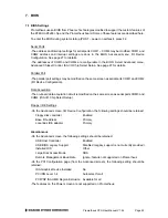
The ISA bus may be configured for standard wait states or zero wait states. In most
configurations and board combinations, the zero wait state setting will work properly and provide
faster performance. However it should be tested in your application to verify correct operation. In
standard configuration, the CPU issues 2 wait states for 16-bit cycles and 3 wait states for 8-bit
cycles.
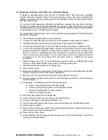
ATX Power Control
The ATX power control is set with this jumper block. If the ATX jumper is out, ATX works
normally; an external momentary switch may be used to turn power on and off. A quick contact
turns the power on, and a long contact (> 4 seconds) turns the power off. If the ATX jumper is in,
the ATX function is bypassed and the system will power up as soon as power is connected.
Erasing CMOS RAM
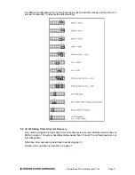
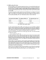
The CMOS RAM may be cleared with a jumper as shown on the next page. This will cause the
CPU to power up with the default BIOS settings. To clear the CMOS RAM, power down the CPU,
install the jumper as shown, return it to its default position, and then power up again.
Before erasing CMOS RAM, write down any custom BIOS settings you have made!
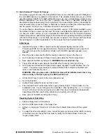
Default Settings


