Prometheus CPU User Manual V1.44
Page 13
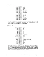
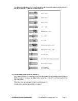
4.8 Floppy Drive – J7
Ground
1
2 High
Density
Ground
3
4 Unused
Ground
5
6 Unused
Ground
7
8 Index
Ground
9
10 Motor
Enable
Ground
11 12
Drive Select B
Ground
13 14
Drive Select A
Ground
15 16 Motor
Enable
Ground
17 18 Direction
Ground
19 20 Step
Ground
21 22 Write
Data
Ground
23 24 Write
Enable
Ground
25 26 Track
0
Ground
27 28 Write
Protect
Ground
29 30 Read
Data
Ground
31 32 Select
Protect
Ground
33 34 Disk
Change
J7 is a 2x17 pin header. It mates with Diamond Systems’ cable no.
698008
or any standard floppy
drive interface cable. Up to two floppy drives can be connected. The connector furthest away from
the others is used to connect to the board. The connector at the far end of the cable (after the
twist) is for Drive A, and the middle connector is for Drive B.
4.9 IDE Drive – J8
RESET-
1
2 Ground
D7
3
4 D8
D6
5
6 D9
D5
7
8 D10
D4
9
10 D11
D3
11 12 D12
D2
13 14 D13
D1
15 16 D14
D0
17 18 D15
Ground
19 20
Key (Not Used)
DRQ
21 22 Ground
IDEIOW-
23 24 Ground
IDEIOR-
25 26 Ground
IORDY
27 28 Ground
DACK-
29 30 Ground
IRQ14
31 32
Pulled low for 16-bit operation
A1
33 34 Not
Used
A0
35 36 A2
CS0-
37 38 CS1-
LED-
39 40 Ground
+5V
41 42 +5V
Ground
43 44 Not
Used
J8 is a 2x22 (44-pin) 2mm-pitch pin header. It mates with Diamond Systems’ cable no.
698004
,
and may be used to connect up to 2 IDE drives (hard disks, CD-ROMs, or flashdisk modules).
The 44-pin connector includes power and mates directly with notebook drives and flashdisk
modules. To use a standard format hard disk or CD-ROM drive with a 40-pin connector, an
adapter PCB such as Diamond Systems’ ACC-IDEEXT is required.


