
JetBox-FloydSC User Manual rev 0.1
Page 27
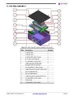
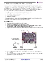
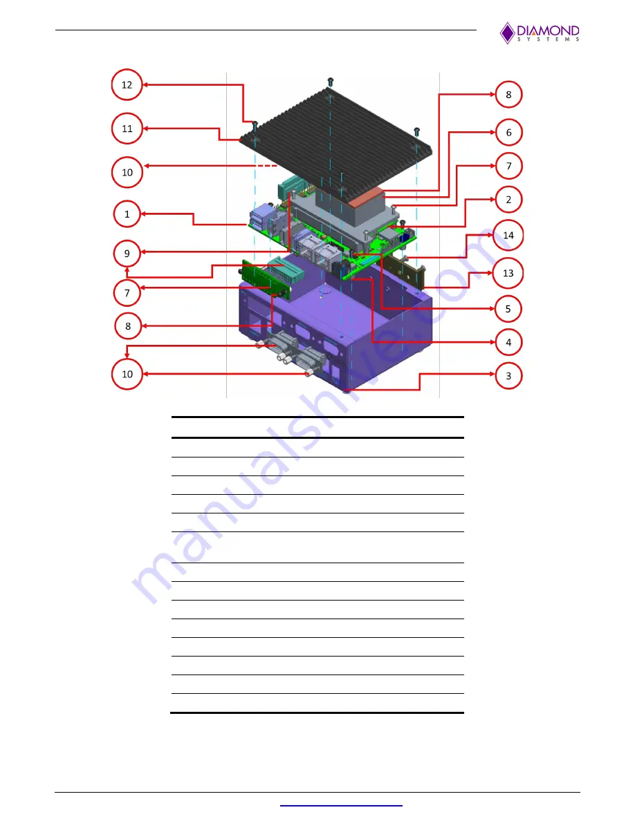
13. SYSTEM ASSEMBLY
Figure 12
JetBox-FloydSC System Assembly Components
Sl No
Description
Quantity
1
FloydSC PCB
1
2
Jetson Module
1
3
Flat Head M3 x 6mm Screws
4
4
M3 x 8mm F/F Stand-offs
4
5
Pan Head M3 x 6mm screws
4
6
JetBox-FloydSC Internal Heat
Spreader with Thermal Pad*
1
7
Pan Head M2.5 x 10mm screws
4
8
JetBox-FloydSC Top sink Thermal Pad 1
9
DSC Cable# 6981330
1
10
DSC Cable# 6981075
1
11
JetBox-FloydSC Top Heat Sink Cover
1
12
Pan Head M3 x 6mm screws
4
13
DIN Bracket
1
14
Flat Heat M3 x 6mm screws
2