


Elton User Manual Rev 1.04
Page 28
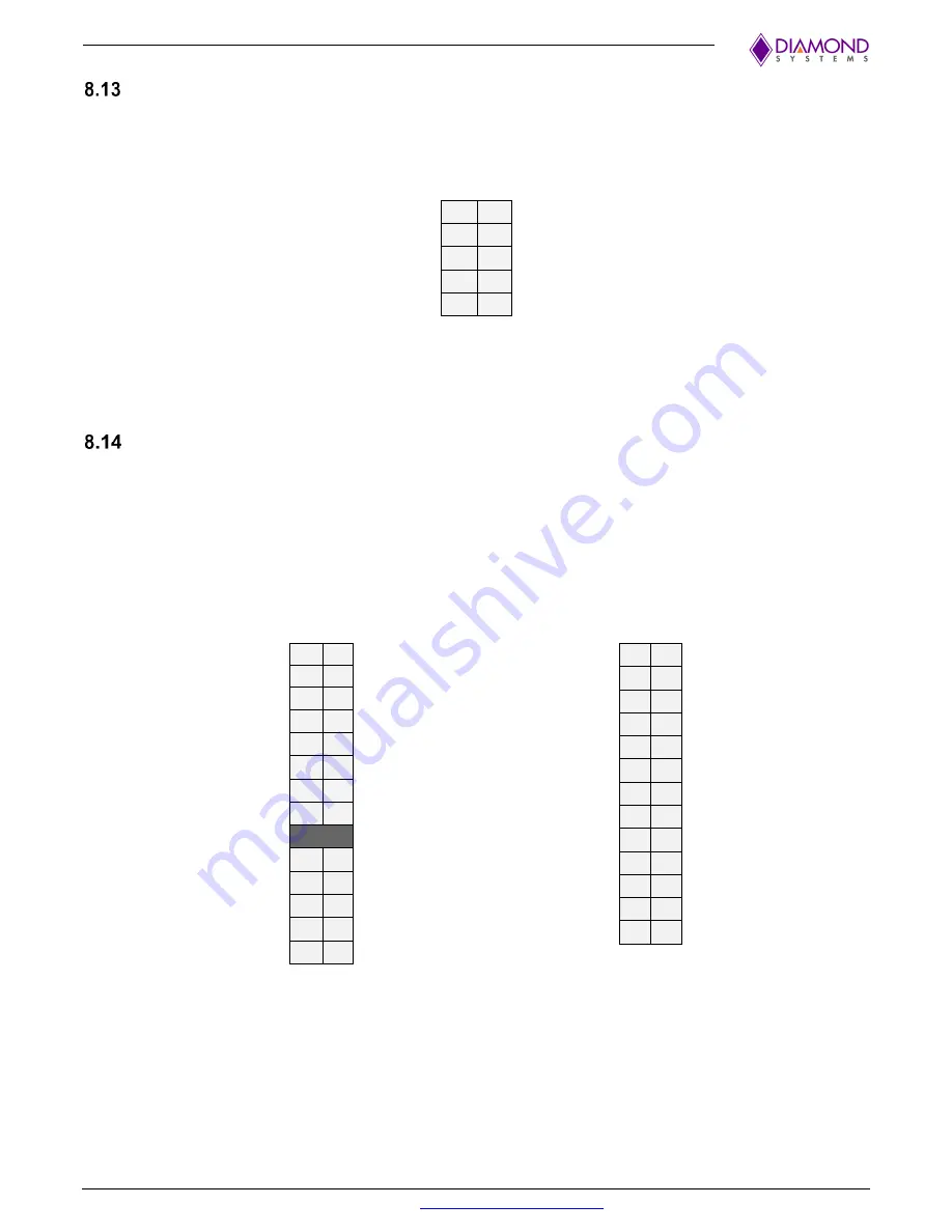
USB 3.1 Port Connectors: J3, J21
Two USB 3.0/3.1 connectors are available on the baseboard. Both are routed from the AGX Xavier Series
Module to the 2x5 Header. The shield pin is tied to the Chassis Ground.
The pinouts for the connector are specified below.
USB_SSRX0-
A01 B01 Shield
US
A02 B02
USB1 Pwr-
USB1 Pwr-
A03 B03
USB2.0 Data+
USB_SSTX0-
A04 B04
USB2.0 Data-
US
A05 B05
USB Pwr+
Connector Type:
2mm Dual-Row; Right Angle Pin Header
Mating Connector Part Number for Latching Connector:
6980603
Mating Cable Part Number for Pin Header:
6980530
PCIe MiniCard Connector: J14
The TX (Transmit) and RX (Receive) signals are transmitted by the host.
The TX signal channels on the socket and the RX signal channels on the AGX Xavier Series Module are bi-
directional. The RX signal on the socket is driven by the TX signal on the installed module and vice versa.
The Chip Select (CS) control feature is available to generate commands on the SPI bus.
The two mounting standoffs at the far end of the AGX Xavier Series Module installation site are not
connected to Ground.
The pinouts are specified below.
1
2
+3.3V
3
4
Gnd
5
6
+1.5V
Clkreq-
7
8
Gnd
9
10
PCIe 1 Clk-
11 12
PCIe 1 Clk+
13 14
Gnd
15 16
KEY
17 18
Gnd
19 20
Disable-
Gnd
21 22
PCIe Reset-
PCIe 1 RX-
23 24
+3.3V
PCIe 1 RX+
25 26
Gnd
Gnd
27 28
+1.5V
Gnd
29 30
SMB Clk
PCIe 1 TX-
31 32
SMB Data
PCIe 1 TX+
33 34
Gnd
Gnd
35 36
Gnd
37 38
+3.3V
39 40
Gnd
+3.3V
41 42
WWAN LED-
Ground
43 44
WLAN LED-
45 46
WPAN LED-
47 48
+1.5V
Pull-up to +3.3V
49 50
Gnd
51 52
+3.3V
Connector Part Number:
MM60-52B1-E1-R650


