background image


MAINTENANCE 

Speed Control Lever 
Adjusting Speed Control Cable 

The forward and reverse functions of the 
speed control system are set at the factory. If 
additional adjustment is needed, there are two 
locations to accomplish this action.  The first is 
located between the upright assembly and 
engine on the left side of the saw.  The cable 
connects to the hydro pump assembly control 
arm. The cable has two jam nuts located on 
the rear engine support to adjust the cable 
length as necessary.  The second location is 
inside the upright where the control cable 
connects to the speed control lever. There are 
two jam nuts at this end of the cable for 
adjustment as well. 

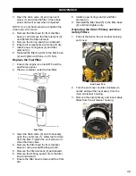
Front Speed Cable Adjustment Nuts 

Rear Speed Cable Adjustment 

Adjusting the Lever Tension 

Adjust the tension felt in the speed control 
lever, when moving the lever forward and 
backward, to the desired setting as necessary. 

1.  Open the rear cover screen. 
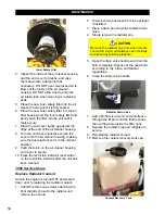
2.  Remove the grease cap from the pivot 

housing. 

3.  Loosen the jam nut on the opposite side of 

the speed control frame using the provided 
wrench. 

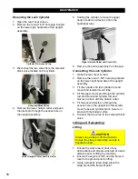
Grease Cap and Jam Nut

4.  Use a 3/8” hex wrench to adjust the 

shoulder screw. 

5.  Retighten the jam nut. 
6.  Move the speed control lever forward and 

backward to test the lever tension. 
Readjust the shoulder screw/jam nut if 
desired. 

7.  Secure the grease cap to the pivot housing. 
8.  Close the rear cover screen and latch. 

Adjusting the Spring Plungers 

Adjust the spring plungers if the speed control 
lever feels floppy or loose when moving the 
lever forward and backward, or when the lever 
is hard to place into or out of the 

STOP/PARK


position. 


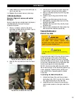
1.  Loosen both hex nuts from the speed 

control tube. 

Spring Plunger Hex Nuts 


54

Summary of Contents for CC5049D

Page 1: ...CORE CUT OPERATOR S MANUAL CC5049D Rev 21 00 Part 1802721...

Page 2: ......

Page 3: ...ures 17 Flat Screen Display 17 Function Keys 19 Soft Key Commands 19 Main Menu Key 20 Engine Diagnostics 21 User Settings 22 Utilities 23 Operation 24 Blade Size Selection 24 Zero the Blade 25 Set the...

Page 4: ...e 33 Water Supply 34 Using the Water Supply 34 Water Pump Optional 34 Automatic Water System AWS Optional 34 Water Pressure Switch Optional 34 Cutting 34 Cutting Guides 34 Adjusting the Front Pointer...

Page 5: ...43 Check Radiator Coolant Level 43 Check and Clean Blade Guard Spray Tubes 44 Lubricate the Blade Shaft Bearings 44 Check Air Cleaner Restriction Indicator 44 25 Hour Service 44 Inspect Belts 44 Lubri...

Page 6: ...Adjusting the Spring Plungers 54 Inner Blade Flange 55 Installing the Inner Blade Flange 55 Removing the Inner Blade Flange 55 Maximum Cutting Depth Stop Bolts 55 Handlebar Lock Cylinder Optional 55 R...

Page 7: ...lt in serious injuries and or death All operators must be properly trained or supervised by experienced personnel prior to using this saw and should understand the risks and hazards involved Diamond P...

Page 8: ...INTRODUCTION CC5049D Controls 8...

Page 9: ...2 Saw Lower Push Button Bleeds hydraulic pressure from lift cylinder to lower saw 13 Tilt Handlebar Button Optional Allows adjustment of handlebars up or down to desired angle 14 Water On Off Control...

Page 10: ...1461 C Saw Length Max 134 3404 D Handle Extension Max 28 711 E Frame Length 47 1 2 1207 F Wheel Base Length 23 584 G Saw Width 37 940 H Rear Frame Width 26 660 I Front Wheels Inside Width 17 1 2 445 J...

Page 11: ...INTRODUCTION CC5049D Specifications 11...

Page 12: ...ARNING Serious injuries and or death could occur if these instructions are not followed CAUTION Mild and or moderate injuries could occur if these instructions are not followed Proposition 65 PROPOSIT...

Page 13: ...uards and access panels unless stated otherwise prior to operating the equipment Always pivot front of blade guard fully closed to avoid serious injuries DO NOT Assume the equipment will remain still...

Page 14: ...immediately DO NOT expose yourself or anyone else to the direct line of the blade when operating the equipment Always use an appropriate size blade and the correct blade type based on the cutting tas...

Page 15: ...w to turn off the engine quickly for emergency purposes Make sure the equipment is in neutral when starting the engine Fill the fuel tank and check the oil level prior to starting the engine Keep all...

Page 16: ...oning belts may cause slippage shorter belt life and or poor equipment performance Squealing belts indicate looseness and must be tightened to proper tension specifications DO NOT use old and new belt...

Page 17: ...the configuration Controller Features Flat Screen Display The flat screen displays the gauges dashboard warning icons soft key commands fault messages and menu options for setup and configuration Ther...

Page 18: ...plied Fuel Level Red icon will illuminate when a low fuel level condition exists Battery Voltage Red icon will illuminate when a low battery voltage condition exists Maintenance Required Yellow icon w...

Page 19: ...below it The soft key options associated with this saw are listed below Soft Key Description Blade Size Toggles to the blade size selection screen Parameter Screen Selection Toggles between Engine Sp...

Page 20: ...down Plus Increases a numerical selection Minus Decreases a numerical selection Return Returns to previous screen Reset Resets the service reminder hours on maintenance milestones when the maintenance...

Page 21: ...red Faults Recall Active Faults This screen displays active faults or warnings from the Electronic Control Unit ECU Each diagnostic is shown with the appropriate Suspect Parameter Number SPN Failure M...

Page 22: ...or FMI Text Description if available and the source of the device that transmitted the diagnostic message User Settings The user setting is a series of two screens that display the following items 1 B...

Page 23: ...in operational when the unit is turned off Only when battery power has been lost will the clock need to be reset and updated Utilities The utilities screen displays the following items 1 Service Remin...

Page 24: ...he ignition switch is turned to ON the display will begin to boot up The first screen to appear will be the Blade Size Selection screen It is important to have the correct blade size selected for the...

Page 25: ...ollowed 1 Lower the saw blade to just above the cutting surface 2 Press the second function key on the right until the top right hand gauge on the display shows 0 00 in The blade is now zeroed When th...

Page 26: ...or to address the emergency condition NOTE Only use the emergency stop in an emergency condition Do not use it to stop the machine during normal operations Activating the Emergency Stop To activate th...

Page 27: ...down to adjust the angle NOTE The button only works with the ignition key at the ON position 4 To reposition adjustment lever pull out and move to desired lever position Speed Control Lever The speed...

Page 28: ...the ignition switch to the ON position 2 Raise the machine by pressing the Raise Left pushbutton on the control grip until the blade clears the pavement 3 Place the speed control lever in the STOP pos...

Page 29: ...for expansion purposes Refer to the engine manual for additional information 5 Replace the fuel tank cap and secure Blade Guard WARNING DO NOT operate the saw with the blade guard raised or removed DO...

Page 30: ...guard and frame base 3 Remove the lock pin from the tapered frame mount 4 Use the handle on the blade guard to rock the guard back and forth while lifting the guard off the tapered frame mount Slurry...

Page 31: ...pposite end of the wrench and tighten the blade shaft bolt screw to 125 ft lb 170 Nm minimum to secure the outer flange and blade NOTE 125 ft lb is equivalent to applying 125 pounds at the end of a 12...

Page 32: ...ft bolt and insert the bolt into the blade shaft through the center of the outer flange 10 Tighten the bolt by hand Slowly lower the saw if necessary until the blade just touches the ground 11 Tighten...

Page 33: ...tton All emergency stop triggers are cleared 1 E Stop active 2 Low coolant level Starting the Engine Note In an emergency press the emergency stop button to immediately stop the engine and any saw mov...

Page 34: ...pump NOTE DO NOT start the water pump until just before cutting DO NOT leave the water pump on when the cutting task is complete to avoid draining the battery 4 Push the water valve to the ON position...

Page 35: ...or to Cutting Keep the following in mind for better efficiency while cutting Use just enough handle pressure to guide the saw down the cutting line DO NOT forcibly direct twist the saw from side to si...

Page 36: ...deep and press the Set Depth Stop button on the display panel Make the initial pass across the entire cutting line using the most effective travel speed If the blade is coming up out of the cut decre...

Page 37: ...nd improve the rear wheel traction when cutting Footrest Weight Bar Optional The weight bar optional adds 56 lb to the rear of the saw to improve the rear wheel traction when cutting 1 Attach the seco...

Page 38: ...nal A heavy duty size 31 battery is an available option that provides greater cranking amps for increased reliability For additional information contact either your local Diamond Products representati...

Page 39: ...safety Ensure all equipment and tools required for the maintenance task are staged and available for use Prior to any maintenance being performed know the locations of all safety equipment such as fir...

Page 40: ...with a lint free cloth Engine Use a mild detergent and water to clean the engine Do not to spray water forcefully on the engine to prevent damage to components NOTE Do not spray water into the exhaus...

Page 41: ...Service Schedule The service schedule is based primarily on the standard operating time of the machine The frequency of the maintenance tasks can be increased based on the working environments of the...

Page 42: ...the saw frame is in a level position 1 With the ignition switch in the ON position the Home screen will appear The fuel level gauge will be displayed on the right side of the display 2 If fuel level i...

Page 43: ...n 3 Remove the hydraulic pump breather cap 4 Using a funnel with flexible hose add SAE15W 40 oil or an equivalent to just below where the fill port extends into the hydraulic pump Do not overfill as t...

Page 44: ...ade shaft bearings The bearings are located under the radiator at the front of the saw 1 Add no more than two pumps of bearing grease into each of the two blade shaft bearing grease fittings Grease Fi...

Page 45: ...tube Do not remove the cap 4 When no more water is discharged re tighten the drainage cap f Fuel Water Separator Filter Drain Water from the Fuel Filter Inspect the fuel filter and drain as necessary...

Page 46: ...of grease to both grease fittings located on the bogie wheel Bogie Wheel Grease Fittings 250 Hour Service Clean the Air Cleaner Element WARNING DO NOT operate the saw without the filter installed 1 E...

Page 47: ...cure 11 Press the restriction indicator reset button on the restriction indicator after the unit has been cleaned Replace Engine Oil and Filter Refer to Engine Operator s Manual for oil and oil filter...

Page 48: ...et is seated Then turn the filter 1 2 turn by hand to secure 8 Reinstall the inlet hose to the filter head and tighten the hose clamp securely 9 Remove the reservoir tank cap 10 Add SAE 15W 40 oil to...

Page 49: ...Filter 3 Open the drain valve 6 and if necessary open the vent screw 1 Allow fuel to drain from the filter Tighten the vent screw and close the drain valve 4 Remove the filter bowl 5 from the filter...

Page 50: ...restriction indicator reset button on the restriction indicator after the unit has been cleaned 1000 Service Hours Replace Radiator Coolant Ensure the engine is turned OFF and cooled down prior to re...

Page 51: ...r breather cap 9 Remove the container and clean away any fluid around the breather assembly Regular Maintenance Blade Drive Belts WARNING Turn off the engine prior to servicing the belts Use extreme c...

Page 52: ...ers to ensure optimal engine performance and efficiency Warning Never weld on the machine with the ECM connected to the wire harness Battery WARNING Ignitable explosive gases are emitted from the batt...

Page 53: ...o tie rod bolts and tighten it using the two ratchet knobs 8 Reconnect the positive cable lead to the positive battery terminal NOTE Always reconnect the positive cable first 9 Reconnect the negative...

Page 54: ...he Lever Tension Adjust the tension felt in the speed control lever when moving the lever forward and backward to the desired setting as necessary 1 Open the rear cover screen 2 Remove the grease cap...

Page 55: ...ss to the maximum cutting depth stop bolts underneath the frame base WARNING Raise the saw to a proper height for access when working underneath the saw Use chocks to block the wheels and fit blocks o...

Page 56: ...e plug located on the lower right hand side of the upright assembly 3 Fit the cylinder into the cylinder rod end mount and isolator mount tube 4 Fit the upper clevis pin through the cylinder rod end m...

Page 57: ...e saw to remove dust debris and slurry from saw components especially fans Remove the battery and store in a proper location out of reach from children Refer to the engine manual for all engine and fu...

Page 58: ...REFERENCES 58...

Page 59: ...REFERENCES 59...

Page 60: ...REFERENCES 60...

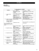
Page 61: ...start switch Replace solenoid on hydraulic pump unit Worn out battery Charge or replace battery Defective raise button Replace raise button Low hydraulic fluid Check hydraulic fluid level and fill as...

Page 62: ...just as necessary Worn sheave grooves Check for groove wear and replace sheaves when necessary Mismatched belts Replace with matched set of belts DO NOT use old and new belts together 9 Blade Speed In...

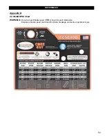
Page 63: ...REFERENCES Appendix B CC5049D RPM Chart WARNING Do not exceed blade speed RPM shown for each blade size Excessive blade speed could result in blade breakage and serious personal injury 63...

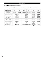
Page 64: ...952 6010954 6010956 6010958 6010960 Blade Shaft Sheave Sheave Size 6012102 4 6010834 4 75 6010175 5 6 6010289 6 9 Drive Belts 8 Belt Size 2500188 3VX560 2503849 3VX570 2503683 3VX580 2503684 3VX600 In...

Page 65: ...ling Association www csda org The CSDA has many helpful concrete cutting publications available to members and non members 4 Association of Equipment Manufacturers www aem org The AEM has a variety of...

Page 66: ...future reference and customer service purposes Serial Number Record the engine s model and serial numbers below for future reference and customer service purposes 1 Model Number Serial Number 1 Note T...

Page 67: ......

Page 68: ...ts Elyria Ohio factory or at a point designated by it of such parts as shall appear to us upon inspection at such parts to have been defective in material or workmanship with expense for transportatio...

Reviews: