Diablo Controls, Inc. Copyright © 2017 Document:
DSP19_MAN_A
Released:
June 05, 2017
Pros Who Know Trust Diablo
User Manual
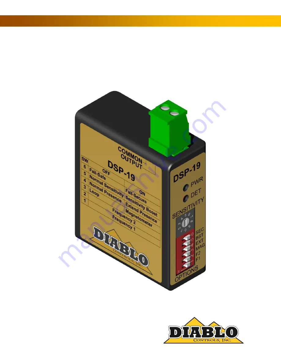
DSP-19
Loop and Mini-Loop Vehicle Detector
Page 1: ...Diablo Controls Inc Copyright 2017 Document DSP19_MAN_A Released June 05 2017 Pros Who Know Trust Diablo User Manual DSP 19 Loop and Mini Loop Vehicle Detector ...
Page 2: ...itivity Boost DIP Switch 5 11 Fail Safe Fail Secure DIP Switch 6 11 Output Connector 12 Indicators 12 4 Installation 15 Detector Installation 15 Loop Installation 15 Mini Loop Installation 18 5 Configuration 20 Wiring 20 6 Troubleshooting 21 No Power LED 21 Power LED Flashes Slowly 2Hz 21 Power LED Displaying 1 Flash On Every Two Seconds 21 Power LED Displaying 2 Flashes On Every Two Seconds 21 Po...
Page 3: ...hysical Dimensions 7 Figure 3 Outputs 11 Figure 4 Power LED States 13 Figure 5 Detect LED States 14 Figure 6 Loop Installation 17 Figure 7 Saw Cut for Home Run Exit and Chiseled Corner for Home Run Exit 17 Figure 8 Typical Mini Loop Installation 18 Figure 9 Mini Loop Side Installation 19 ...
Page 4: ...icles Contact Diablo Controls for more information on the mini loop The DSP 19 can be used as either a safety loop or free exit loop detector It also has the flexibility to be either fail safe or fail secure The DSP 19 has a single solid state FET output The DSP 19 has 10 selectable sensitivity settings and uses a 6 position DIP switch to configure the detector This includes the Diablo Controls mi...
Page 5: ...uctive Loop Response Time Response time is dependent on the sensitivity selected Setting Response Time Setting Response Time 0 70ms 10ms 5 70ms 10ms 1 70ms 10ms 6 140ms 20ms 2 70ms 10ms 7 140ms 20ms 3 70ms 10ms 8 140ms 20ms 4 70ms 10ms 9 140ms 20ms Mini Loop Response Time Response time is dependent on the sensitivity selected Setting Response Time Setting Response Time 0 130ms 10ms 5 130ms 10ms 1 ...
Page 6: ...e wide range power version 8 volts to 35 volts DC Solid State Output Rating Maximum Output Current 250 milliamps Maximum Pull Up Voltage 30 volts Maximum Voltage Drop Across Active Output 0 3 volts Current Draw Without detection is 31 ma maximum With detection is 40 ma maximum Environmental Data Operating Temperature 35 F to 165 F 37 C to 74 C Storage Temperature 40 F to 176 F 40 C to 80 C Humidit...
Page 7: ... 7 of 24 DSP19_MAN_A Mechanical Data Mounting Position Any Housing Material Lexan Housing Size 2 362 inches High x 2 008 inches Wide x 866 inches Deep 60 00 mm High x 51 00 mm Wide x 22 00 mm Deep Figure 2 Physical Dimensions ...
Page 8: ...he polarity issue is handled by the operator if the detector plugs directly in to the operator If using an adapter board like the RK 1 or RK 3 the negative side of the output is already connected to DC common So the output is simply connected to the desired termination point on the controller and it should all work The easiest way to envision the function of a solid state open drain output is to t...
Page 9: ...put is always configured for pulse on entry operation The pulse generated by the main output will be 250 milliseconds long It is intended that there will be one output pulse for each car driving over the loop However if a vehicle remains over the detection area for longer than two seconds a second pulse will be generated when the vehicle exits the area NOTE The magnetometer mode of operation can n...
Page 10: ...apable of operating with either a standard inductive loop in the presence mode or the new mini loop magnetometer in the pulse on entry mode In the magnetometer mode of operation the detector will only hold a detection for 2 seconds Therefore if a vehicle stays over the sensor for more than 2 seconds it may generate additional pulses for the same vehicle The factory default is the inductive loop mo...
Page 11: ...er starting sensitivity and then increase it after a vehicle has been detected This is useful in situations where high bed tractor trailer vehicles will be passing over the loop With this feature the detector may be able to detect the high bed portion of the vehicle without having to be overly sensitive and susceptible to false detections NOTE If detection of high bed tractor trailers is required ...
Page 12: ...p inputs and power inputs However the main output is through the 2 pin connector located on the top of the detector The connector is a typical Euro style screw terminal block Looking straight on at the side label the wires are inserted in the opposite side of the connector and then torqued down with the appropriate screw As the label denotes the right most screw is the main output and the left mos...
Page 13: ...50 milliseconds every two seconds LARGE CHANGE FAULT When the detector senses that a loop is experiencing a large inductance change greater than 30 the LED will flash on three times for 150 milliseconds every two seconds PRIOR FAULT The detector is equipped with the ability to remember prior faults that have occurred since the last power interruption or reset changing a DIP switch or the sensitivi...
Page 14: ... the LED will turn off for 500 milliseconds on for 500 milliseconds off for 500 milliseconds on for 500 milliseconds and then finally display its normal state The main output will be activated during this time Reset in Fail secure At the start of a reset event a DIP switch change sensitivity change or power cycle the LED will turn off for 500 milliseconds on for 500 milliseconds blink repeatedly w...
Page 15: ...d state outputs and can only sink current Therefore if you want to drive a relay coil with an output the other side of the relay coil must be connected to an appropriate voltage for the coil positive DC supply Using an AC relay is not possible and may damage the detector The detector has snubber diodes built in for all of the solid state open collector outputs in case they do drive a relay coil Lo...
Page 16: ...nto the road surface using a saw with an appropriate cutting disk for the road surface The slot cut should be wide enough that the wire being used will easily fit into the slot This is needed so that the loop sealant used can fully encapsulate the wire When the wire fits tightly in the slot the sealant may not be able to get below the wire leaving air pockets in the saw slot If water finds its way...
Page 17: ...DSP 19 User Manual Page 17 of 24 DSP19_MAN_A Figure 6 Loop Installation Figure 7 Saw Cut for Home Run Exit and Chiseled Corner for Home Run Exit BACKER ROD PIECE LOOP WIRE SAW CUTS DETAIL A DETAIL B ...
Page 18: ...ction possible from foreign object penetration Never use a continuous piece of backer rod over the loop as this would prevent the loop sealant from encapsulating the loop wire The loop sealant used should be appropriate for the roadway surface that was cut Generally epoxy or polyester based sealants are used for concrete surfaces and polyester or urethane based sealants are used for asphalt surfac...
Page 19: ...ide of the roadway and achieve acceptable detection performance The Mini Loop can be installed at a 45 degree angle so that the top of the sensor points towards where the vehicle is to be detected This can be very useful when applications where there is already an existing driving surface that the customer does no want distrubed Figure 9 Mini Loop Side Installation When the roadway is greater than...
Page 20: ...5 Configuration Wiring There is only one wiring configuration pin out offered for the DSP 19 Pin Function 1 Loop or Mini Loop 2 Loop or Mini Loop 3 No Pin 4 Not Connected 5 Not Connected 6 Not Connected 7 Not Connected 9 DC 10 DC and Output Common ...
Page 21: ...he pin out If a loop is connected to the correct pins of the detector disconnect the loop and using an ohmmeter check the resistance of the loop circuit If the resistance is above 5 ohms there is a bad connection or the wire has been damaged The resistance will typically be 1 5 ohms or less If the resistance is below 5 ohms the loop inductance should be checked This is done using an inductance met...
Page 22: ... loops may also have a low inductance value if sufficient turns were not added Contact technical support for help with very small loops If you do not have a meter capable of measuring resistance and inductance but do have another operating detector in the same control box you can skip to this step Swap the loops between a working detector and a failing detector If the problem follows the loop the ...
Page 23: ...ys On Without a Vehicle Present This type of symptom is usually caused by one of three issues physical issues with the loop electrical interference moving objects in proximity to the loop Physical Issues with the Loop There are many ways in which a loop installation can go bad The insulation of the loop wire can fail This can be due to the loop wire being exposed in the saw lot damage to the wire ...
Page 24: ...vel so that the desired vehicles are still detected but not the moving gate NOTE Do not lower the sensitivity too much or vehicles will no longer be detected Another possibility is metal objects in close proximity to the loop Utility manhole covers are objects that may move slightly when vehicle tires drive over them especially if the vehicle turns while a tire in on the cover Most manhole covers ...