36
DHOLLANDIA
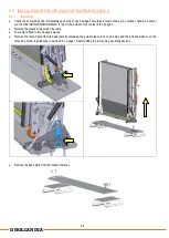
On DH-AI13.04.01 ramps, the support feet can be dismounted and moved up / down.
Deploy the ramp in its open work position.
Dismount the bolts that hold the support feet to the side platform profile.
Extend or retract the support feet so that:
1.
the subsequent platform sections are fully aligned and form one straight surface.
2.
the support feet are in firm contact with the ground.
If the holes in the tubes don’t line up with the positions in the side platform profile when the platform sections are fully aligned,
lower the platform slightly, take the next hole up and make the support feet slightly too short. Make sure that in final position,
the tip of the flip-over point touches the ground.
Mount the bolts again and fasten the bolts and nuts with the required torque. See appendix 11.2 on page 42.
9.3.2
Support rod on ramps with the optional pivoting frame [OAF820.L]
The pivoting frame [option OAF820.L] is equipped with a support rod, holding the platform upright during the pivoting movement.
Adjusting the length of the rod influences the angle of the platform during the pivoting movement and its ability to swing in and
out.
To adjust:
-
Loosen the counter-nuts.
-
Turn the rod by means of a wrench.
-
Test the ramp in the various closed positions across the rear doors, pivoted inwards and outwards. Adjust further if needed.
-
Retighten the counter nuts firmly after fine-tuning.
Summary of Contents for DH-AI02.04.01
Page 10: ...9 DHOLLANDIA DH AI12 04 01 TERMINOLOGY DH AI13 04 01 TERMINOLOGY...
Page 11: ...10 DHOLLANDIA DH AI12 10 01 TERMINOLOGY Portable ramp DH AI02 04 01 TERMINOLOGY...
Page 15: ...14 DHOLLANDIA 7 4 TECHNICAL SPECIFICATIONS DH AI12 04 01...
Page 16: ...15 DHOLLANDIA DH AI12 10 01...
Page 17: ...16 DHOLLANDIA DH AI13 04 01...
Page 18: ...17 DHOLLANDIA DH AI02 04 01...


