background image


2 Modbus-RTU Control 

2.1 Wiring 


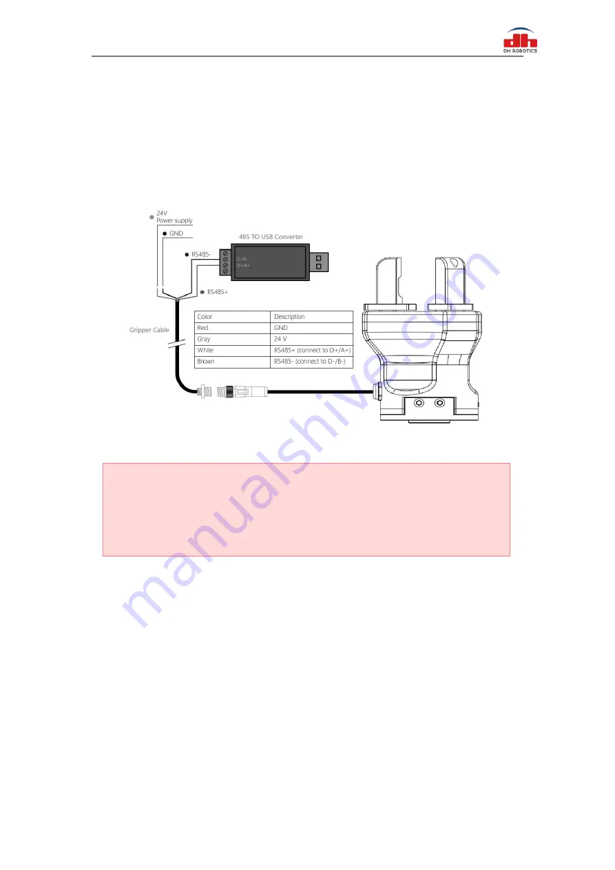
Use the provided RS-485 to USB converter (see the schematic in Figure 1.1 below) to plug 

into a PC or other Controllers. 


Figure 2.1 RS485 Connection 


2.2 Default Communication Parameters 


Slave Address 


Baud Rate 

115200 


Data Bits  

8 bits 


Stop Bits  

1 stop bit 


Parity 


None   

Warning 


·

Please check the connector before inserting, and do not forcibly insert the plug. Even if 

the cable connector has a fool-proofing design, but you can still forcibly insert it, then the 
gripper would be damaged. 


Summary of Contents for CGC-80

Page 1: ...2 3 3 Register Mapping 7 2 3 4 Register Description 9 2 3 4 1 Initialization 9 2 3 4 2 Force 9 2 3 4 3 Position 10 2 3 4 4 Speed 10 2 3 4 5 Initialization State 11 2 3 4 6 Gripper State 11 2 3 4 7 Current Position 12 2 3 4 8 Save Parameter 12 2 3 4 9 Initialization Direction 12 2 3 4 10 Slave Address 13 2 3 4 11 Baud Rate 13 2 3 4 12 Stop Bits 14 2 3 4 13 Parity 14 2 3 4 14 Test I O Parameters 15 ...

Page 2: ...2 3 2 2 Open IO 20 3 2 3 Save Settings 20 3 2 4 Restart 20 ...

Page 3: ...1 Revisions Date Version Revised content 20200426 V1 0 First edition write wiring instructions and command instructions 20200904 V2 0 Change some instructions Update the description of IO mode ...

Page 4: ... and speed Multiple communication modes The gripper supports Modbus RTU protocol and IO mode control Other communication protocols such as Ethernet and ETHERNET can be transferred through protocol converter Gripping Detection The combination of force control and position control is adopted in the gripping process Gripping feedback The state of the gripper can be read by programming and can also be...

Page 5: ...angle and gripping position into account The following right angle coordinate system is established and the corresponding directions of the X axis Y axis and Z axis are shown in Figure 1 2 below The force perpendicular to the gripped flat surface is used as Fz the x axis direction torque is Mx the y axis direction torque is My and the z axis direction torque is Mz The CGC 80 finger load table is s...

Page 6: ...imension drawing of CGC 80 Figure 1 3 b Dimension of CGC 80 guide rail Color description of indicator light Uninitialized state Red light blinks other lights are off Initialized State the blue light is always on indicating that it is in the operable state Received command state the red light blink once quickly because the blue light is always on at this time the gripper indicator light will looks ...

Page 7: ...s 0 Figure 1 4 Standard flange according to ISO 9409 1 50 4 M6 1 5 Pinout Description The pinout of the gripper is shown in Figure 1 5 and the pin description is shown in Table 1 3 Figure1 5 Pinout assignment Table 1 3 Pinout assignment Wire number Wire color Description 1 White 485_A 2 Brown 485_B 3 Green OUTPUT 1 4 Yellow OUTPUT 2 5 Grey 24 V 6 Pink INPUT 2 7 Blue INPUT 1 8 Red GND 2 1 7 6 5 4 3...

Page 8: ...re 2 1 RS485 Connection 2 2 Default Communication Parameters Slave Address 1 Baud Rate 115200 Data Bits 8 bits Stop Bits 1 stop bit Parity None Warning Please check the connector before inserting and do not forcibly insert the plug Even if the cable connector has a fool proofing design but you can still forcibly insert it then the gripper would be damaged ...

Page 9: ...lls the addressed slave what function to perform Includes read or write registers function Register address Specifies which registers reference to be written Register data Specifies which value to be written Each register word 16 bits of the Modbus RTU protocol is composed of 2 bytes 8 bits from the Gripper CRC the CRC error checking field contains a 16 bit value implemented as two eight bit bytes...

Page 10: ...ect caught 3 Object dropped Position 0x02 gripper position Read Only Current actual position Table 2 3 Configuration register map Function High byte Low bytes Description Write Read Save Parameter 0x03 0x00 Save all the parameters 0 default 1 Write all parameters to save 0 Initialization direction 0x01 Configure initialization direction 0 Open 1 Close default 0 Current setting Slave Address 0x02 C...

Page 11: ...ss Description Write Read Initialization 0x0100 Initialize the gripper 0x01 initialize 0xA5 Fully initialize Current setting The gripper needs to be initialized before control The sample command is as follows Initialize write Send 01 06 01 00 01 49 F6 Receive 01 06 01 00 01 49 F6 Reinitialize write Send 01 06 01 00 00 A5 48 4D Receive 01 06 01 00 00 A5 48 4D 2 3 4 2 Force This register is used to ...

Page 12: ...alue is 00 00 03 E8 Hexadecimal Example Set 500 position write Send 01 06 01 03 01 F4 78 21 Return 01 06 01 03 01 F4 78 21 Read the reference position currently set read Send 01 03 01 03 00 01 75 F6 Return 01 03 02 xx xx crc1 crc2 2 3 4 4 Speed This register is used to set the Gripper closing and opening speed The address is 0x0102 The description of this register is shown in Table 2 7 Table 2 7 S...

Page 13: ...pper state you can get the state of gripper by reading this register And the address is 0x0201 The description of this register is shown in Table 2 9 Table 2 9 Gripper State Function Address Description Write Read Gripper State 0x0201 the gripper state Read Only 0 In motion 1 Reached position 2 Object caught 3 Object dropped Example Read gripper state read Send 01 03 02 01 00 01 D4 72 Return 01 03...

Page 14: ...f you modified the I O or communication parameters The address is 0x0300 The description of this register is shown in Table 2 11 Table 2 11 Save Parameter Function Address Description Write Read Save Parameter 0x0300 Save register s value to Flash 0 default 1 Save all parameters 0 Example Save Parameter Write Send 01 06 03 00 00 01 48 4E Return 01 06 03 00 00 01 48 4E 2 3 4 9 Initialization Direct...

Page 15: ...00 D8 4E Return 01 06 03 01 00 00 D8 4E 2 3 4 10 Slave Address This register is used to set Slave Address of gripper The address is 0x0302 The description of this register is shown in Table 2 13 Table 2 13 Slave Address Function Address Description Write Read Slave Address 0x0302 Configure gripper Slave Address 0 255 default 1 Current setting The value of this register is 1 by default Example Set ...

Page 16: ...ddress Description Write Read Stop Bits 0x0304 Configure gripper Modbus stop bits 0 1 stop bit 1 2 stop bits default 0 Current setting The value of this register is 0 by default corresponding to 1 stop bit Example Set the gripper stop bit to 1 stop bit write Send 01 06 03 04 00 00 C8 4F Return 01 06 03 04 00 00 C8 4F 2 3 4 13 Parity This register is used to set Parity of gripper The address is 0x0...

Page 17: ...g first group of I O parameter write Send 01 06 04 00 00 01 49 3A Return 01 06 04 00 00 01 49 3A 2 3 4 15 I O Mode Switch This register is used to turn I O Control Mode ON or OFF The address is 0x0402 The description of this register is shown in Table 2 18 Table 2 18 I O Mode Switch Function Address Description Write Read I O Mode Switch 0x0402 I O Control Switch 0 OFF 1 ON Current setting If you ...

Page 18: ...1 100 I O Group 3 0x0B position 3 0 1000 0x0C force 3 20 100 0x0D speed 3 1 100 I O Group 4 0x0E position 4 0 1000 0x0F force 4 20 100 0x10 speed 4 1 100 Example Set the first group of I O parameter write Send 01 06 04 05 01 2C 98 B6 Reference position 300 Return 01 06 04 05 01 2C 98 B6 Send 01 06 04 06 00 1E E8 F3 Force 30 Return 01 06 04 06 00 1E E8 F3 Send 01 06 04 07 00 1E B9 33 Speed 30 Retur...

Page 19: ...sition 20 force 10 speed Group 2 100 position 20 force 2 speed Group 3 0 position 100 force 5 speed Group 4 592 position 100 force 10 speed Send 01 10 0405 000C 18 03e8 0014 000A 0100 0014 0002 0000 0064 0005 0250 0064 000a 9f 44 Return 01 10 04 05 00 0C D1 3D ...

Page 20: ...ble 3 2 Table 3 2 Output1 Output2 State I O State OUT1 OUT2 State description 0 0 Fingers are in motion 1 0 Fingers are at reference position No object detected or object has been dropped 0 1 Fingers have stopped due to an object detection The four states of IO mode can be configured through Modbus RTU protocol of RS485 or the parameters of gripper can be configured through our debugging software ...

Page 21: ...meter Configuration to configure four groups of IO parameters It is recommended to use serial port debugging software at PC for configuration IO parameters are configured as continuous address and 12 groups of data including 0x0405 0x0410 need to be set You can configure the IO parameters of the gripper in two ways as follows The first way Use the test software of the gripper for configuration As ...

Page 22: ...cific instructions are as follows Send 01 06 04 02 00 01 E8 FA Return 01 06 04 02 00 01 E8 FA 3 2 3 Save Settings Save the configured parameters and write 01 at the register of 0x300 for saving Send 01 06 03 00 01 48 4e Return 01 06 03 00 01 48 4e 3 2 4 Restart After power off you can connect the input and output to the corresponding equipment and power on after confirming that the wiring is corre...

Reviews: