20
User's Manual |
KS-SD
Chapter 5
Chapter 5 - Ports and Connectors
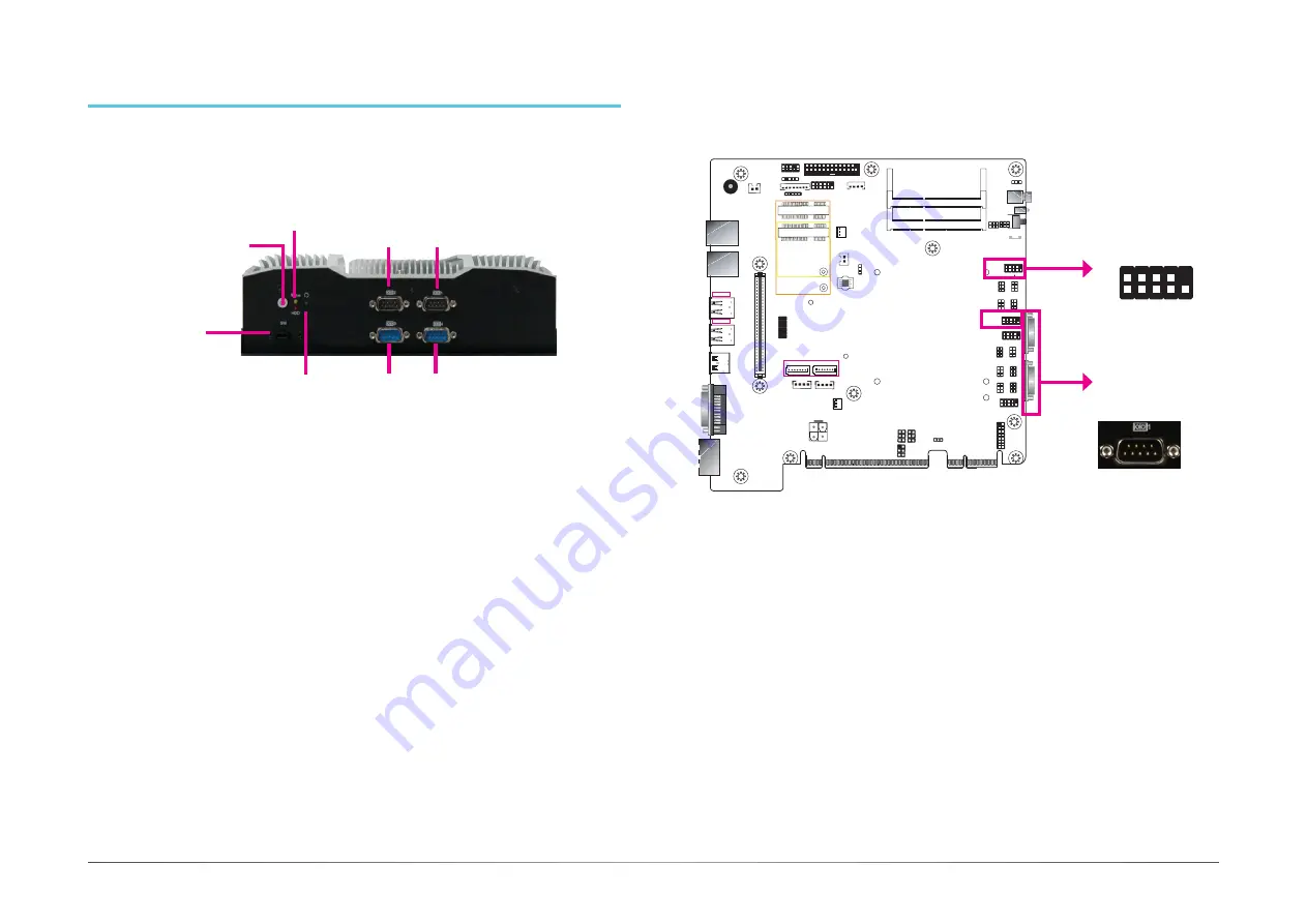
Bottom Panel I/O Ports
The bottom panel I/O consists of the following ports:
• Power button with LED (green)
• Reset button
• Remote power on/off switch connector
• Status and HDD LEDs (orange/red)
• Four RS232 serial ports
COM 2
Power Button
(Green LED)
Reset Button
COM 3
COM 4
Status LED (Orange)
HDD LED (Red)
COM 1
Remote Power-on
Switch
Buzzer
USB 3-4
USB 3.0
USB 1-2
USB 3.0
Power LED
HDD LED
J22
JP2
JP3
J21
HDMI (default)/DP
DVI
System
Fan 2
1
Front
Panel
5
1
1
1
1
1
4
SATA Power
-
DC-in
LAN 2
LAN 1
PCIe x16 (PCIE1)
SPI Flash
BIOS
9
1
2
10
COM 4
VGA
1
6
(JP4)
Clear CMOS
Data (JP1)
Auto Power-on
Select (JP11)
1
6
(JP9) (JP16)
1
6
6
1
(JP8) (JP15)
1
6
6
1
(JP10)
1
2
10
COM 3
1
(JP6)
6
6
9
1
2
10
COM 2
9
1
2
(JP7) (JP14)
6
6
1
2
1
2
10
COM 1
9
1
2
16
LPC
1
2
14
4-pin DC-out
1
1
2
3
4
PCIe x4 (PCIE2)
Power Button
Reset
DDR4_2 SODIMM
DDR4_1 SODIMM
1
(JP5)
6
6
1
1
1
6
6
2
2
2
6
1
4
STB_LED
2
25
26
Parallel
1
DIO Power
DIO
S/PDIF
Front Audio
2
5
1
1
10
9
ECX
+
SATA 3.0
(JP13)
1
1
(JP12)
1
SATA 0
SATA 1
1
Mini PCIe
mSATA
System
Fan 1
1
1
bettery
1
1
1
2
12
USB 2.0
9
COM 2
COM 1
COM (Serial) Ports
COM1 to COM4 can be selected among RS232, RS422 and RS485. In addition, COM1 and
COM2 can be switched between standard RS232 and RS232 with power. For pin definitions and
jumper selection of different communication modes, please refer to Chapter 4.
The serial ports are asynchronous communication ports with 16C550A-compatible UARTs that
can be used with modems, serial printers, remote display terminals, and other serial devices.
•
BIOS Setting
Configure the serial ports in the Advanced menu (“Super IO Configuration” submenu) of the
BIOS. You can use the BIOS setup utility to configure RS485 auto flow mechanism. Refer to
Chapter 7 for more information.
COM1 to COM4:
RS232/RS422/RS485
2
1
9
RXD
DCD TXD
DT
R
GND
DSR
RT
S
CTS
RI
COM1 to COM4:
RS232/RS422/RS485


