5 YEAR
W
ARRANTY
DOVER FLEXO ELECTRONICS, INC.
ISO 9001 CERTIFIED
INSTRUCTION MANUAL
T
T
RUE ENSION
™
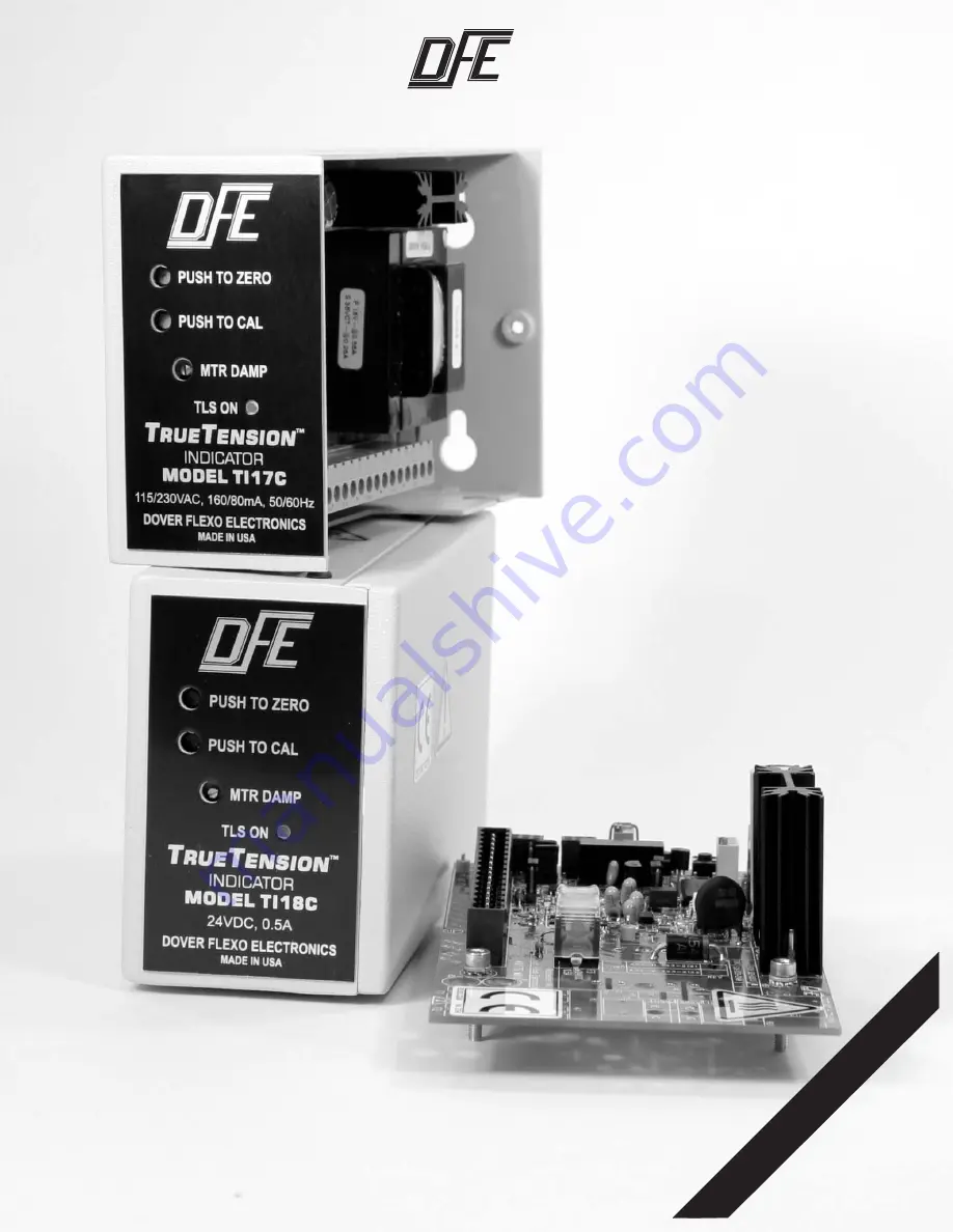
TENSION INDICATOR
Models TI17C and TI18C
with Quik-Cal
™
Model TI17CV
in Vertical Mounting Bracket
Model TI18CV-COV
in Vertical Mounting Bracket with Cover
Model TI18CH
Horizontal Card


