DS-CAM 600
TECHNICAL REFERENCE MANUAL
4.2. Connections
4.2.1. Connectors and pinout
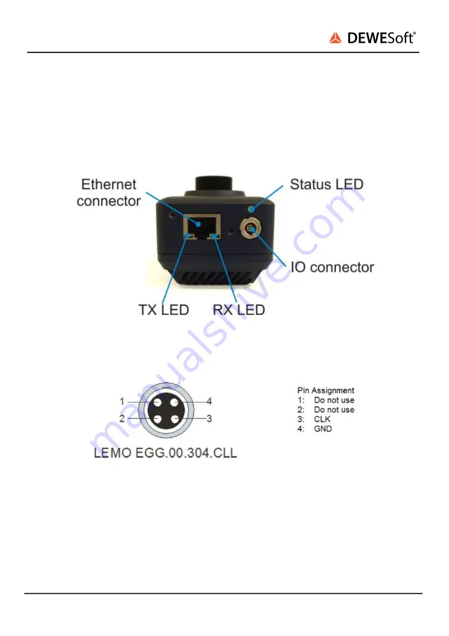
On the backside of the camera there are two connectors. For the trigger input there is a 4 pin Lemo 00
(called “IO connector”), for the data transfer an Ethernet connector. The pinout of the Ethernet
connector is according to the standard.
Illustration 2: Connectors
Illustration 3: IO connector pinout
Note that pins 3 and 4 are used for clocking the camera. Pins 1 and 2 are reserved for synching multiple
DEWESoft instruments!
4.2.2. SIRIUS connection example
In this picture you see a typical SIRIUS device consisting of a S-Box unit (integrated PC) on bottom and
one SIRIUS slice on top (from rear side).
DS-CAM 600 V20-1
7/27


