background image

Trims and Virtual Inputs (Standard & Advanced GUI)

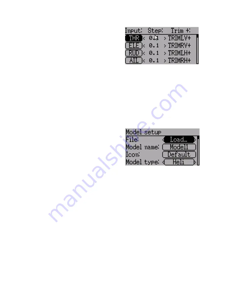
The trim page allows assigning the trim
buttons and trim step, as well as configuring
buttons to work as virtual inputs.  It s accessed
from the main menu via 'Model menu'
followed by 'Trims'.

If the ‘Input’ field is set to an input stick, then
the trim is applied as part of the mixer, and
will operate as a typical trim control.  If the ‘Input’ field is set as a channel or virtual-
channel output, the value is applied directly to the channel output.  In this case, the 
selected ‘Pos’ and ‘Neg’ buttons can operate as a virtual stick to control an output 
channel.

The Trim-step defines how sensitive the trims are to input.  The maximum number of 
trim steps is +/-100.  So a step size of 0.1 will allow a full +/- 10% of trim adjustment on 
the servo.

Model Setup Page (Standard & Advanced GUI)

The model page provides various model
configuration options.  It s accessed from the
main menu via 'Model menu' followed by 'Model
setup'.

File

: The File spin-box allows loading a new model, copying the existing model to a new 

location, resetting the current model to the default (all configuration is lost), and loading 
templates (see Predefined Templates)

Model Name

: Set the model’s name

Icon

: Choose the model’s icon

Model Type

: Set the model type.  Some models (e.g. helicopter) have additional 

configuration options that can be accessed by clicking the Model type.

Protocol

: Set the type of Rx being used.  Note that some protocols have additional 

options that can be accessed by pressing the Protocol spin-box when it is active.  See the 
Protocol section for more on specific protocols.  Note that a protocol change will take 
effect immediately and could cause a bound model to behave erratically.

Number of channels

: Sets the number of channels to transmit (the maximum number of 

channels is dependent on the selected protocol).

Tx Power

: Specify the radio output power when applicable.

Fixed ID

:  The Fixed ID sets a unique code to ensure that the Tx will only bind to a 

specific model.  This is useful to ensure that the Tx is not accidentally bound to the 
wrong model.

Bind/Re-Init

:  Depending on the protocol and Fixed-ID setting, the Tx may bind with the

model on start-up, or may need to be manually bound once.   See the Protocol section for 

Page | 21 

Summary of Contents for Devo10

Page 1: ...Deviation Firmware for Devo7e 10 User s Manual Version 3 0...

Page 2: ...Settings 11 Main Page Configuration Standard Advanced GUI 12 Preview 12 Trim Positions 12 Boxes 12 Switch Display 12 Quick page Selection 12 Mixer Advanced GUI 13 Simple Template 14 Expo Dual Rate Te...

Page 3: ...Advanced GUI 27 Telemetry Configuration Page Standard Advanced GUI 28 Standard GUI 29 Servo Reverse Standard GUI 29 Sub trim Adjustment Standard GUI 29 Servo Travel Adjust Standard GUI 30 Swash Confi...

Page 4: ...rough text files which the firmware or user can read and write It is easy to know exactly what is configured as well as to modify the configuration either through the transmitter or with a text editor...

Page 5: ...tool You will need the Devention DfuSe USB Upgrade Tool from Walkera http www walkera com en upload upgrade 2013 2 26 rar Do NOT attempt to use the DfuSe tool from STMicroelectronics It is recommende...

Page 6: ...strongly recommended to back up the models directory from the transmitter as well as the tx ini file to ensure you don t lose any model or transmitter configuration Next unzip the deviation fs devoXX...

Page 7: ...ew files It is therefore necessary to have a modelxx ini for each model regardless of whether it is currently in use modelico bmp All available model icons must be 96x96 pixels templates ini Configura...

Page 8: ...e Displays These can be text boxes contacting input channel telemetry or timer data bar graphs displaying channel data or icons displaying specific states e g gear flaps Model Icon An image representi...

Page 9: ...value selection On all menu pages UP and DN are used to navigate to the previous next item The R and L buttons are used on spin box widgets to increase or decrease the selected value In some cases ho...

Page 10: ...al stick Aileron in mode 2 R F Right Horizontal trim z Gear x Rudder Dual Rate switch c Elevator Dual Rate switch v Aileron Dual Rate switch b Mix 0 1 2 switch n FMode 0 1 2 switch Power off Left arro...

Page 11: ...r and Rudder on right Sticks Calibrate the range of all analog sticks and dials Buzz Settings Buzz volume Set buzzer volume Vibration Turn haptic feedback on off Batt alarm Set battery voltage at whic...

Page 12: ...side Only 4 trims are shown and they are placed at the middle of the screen 6 Trims 6 trims are shown all placed towards the inside Boxes Boxes are used to display interesting text values There are 8...

Page 13: ...single input an activation switch and a function curve that modifies the mixer output This is a very powerful capability but it is requires a lot of understanding to make full use of In order to simp...

Page 14: ...ent mixer settings making it possible to test them on the transmitter Src The input source controlling this mixer Curve The function applied to the input to generate the output See the Curve section f...

Page 15: ...ed or alternatively can have an independent curve definition Pressing the Mid Rate or Low Rate button for a given switch will toggle between linked and independent curves A Long ENT press will update...

Page 16: ...the previous mixers Mult Multiply the value of this mixer with the previous mixers Max The output will be the greater of the current mixer vs the previous mixers Min The output will be the lesser of t...

Page 17: ...se 0 if Switchn 1 Mn 1 else 0 if Switch0 M0 else 0 For a Max mux Cx MAX if Switchn Mn else 0 if Switchn 1 Mn 1 else 0 if Switch0 M0 else 0 For a Min mux Cx MIN if Switchn Mn else 0 if Switchn 1 Mn 1 e...

Page 18: ...mixer and use the up down buttons to move the order of the selected mixer Note that the mixer name rep resents its position when the reorder dialog was opened If the dialog is closed and re opened al...

Page 19: ...ve Editor is accessed by pressing a graph or by pressing the curve spin box when it is selectable Some curve types may not be edited any of the curves preceding the Expo curve and the curve box will n...

Page 20: ...lsafe Specifies a value that the Rx should use when it loses signal from the transmitter Not all receivers support this capability Safety Specifies a switch that will override all mixers and force the...

Page 21: ...l to a new location resetting the current model to the default all configuration is lost and loading templates see Predefined Templates Model Name Set the model s name Icon Choose the model s icon Mod...

Page 22: ...VO protocol also supports enabling disabling the telemetry capability This option is accessed by pressing the Protocol spin box when DEVO is shown Protocol WK2801 The WK2801 protocol is used to contro...

Page 23: ...does not prevent auto binding during power on Protocol DSM2 The DSM2 protocol is used to control many Spektrum and JR as well as other models using this protocol While the DSM2 protocol can support up...

Page 24: ...er will attempt to auto bind with the receiver every time it is powered on If a value is set for FixedID the receiver must be bound manually one time using the Bind button after which it should stay b...

Page 25: ...fore the first use The Frsky2way protocol also supports enabling disabling the telemetry capability This option is accessed by pressing the Protocol spin box when Frsky2way is shown Protocol Skyartec...

Page 26: ...ed Templates The Deviation firmware supports user customizable predefined templates By Selecting Template From the Model page it is possible to select one of these options Additional templates can be...

Page 27: ...either manually from the main screen or by an input trigger stick or switch Timers can also be optionally configured to be reset via an alternate switch only when using the Advanced GUI The permanent...

Page 28: ...occur This page is accessed from the main menu via Model menu followed by Telemetry Telemetry Specify the telemetry input to use for alarm control This can be a temperature probe voltage probe or RPM...

Page 29: ...ration See page 31 10 Swash Swash Setup See page 30 11 Fail safe Fail Safe configuration See page 31 12 Switch assignment Assign switch controls See page 31 13 Timers Timer configuration See page 27 1...

Page 30: ...degree swash 3Servo 120x 120 degrees swash alternate config 3Servo 140 140 degree swash 3Servo 90 90 degrees swash Dual Rate Expo setting Standard GUI The dual rate and expo page allows configuration...

Page 31: ...l as which channel to use for sending the gyro value Switch Assignment Standard GUI The switch assignment page enables configuring which switches to use for each capability in the standard GUI The sam...

Reviews: