background image

3. Periodical check

Field Service Ver. 1.0 Apr. 2005

8

ineo 161

ineo 210

Maintenance

B. Option

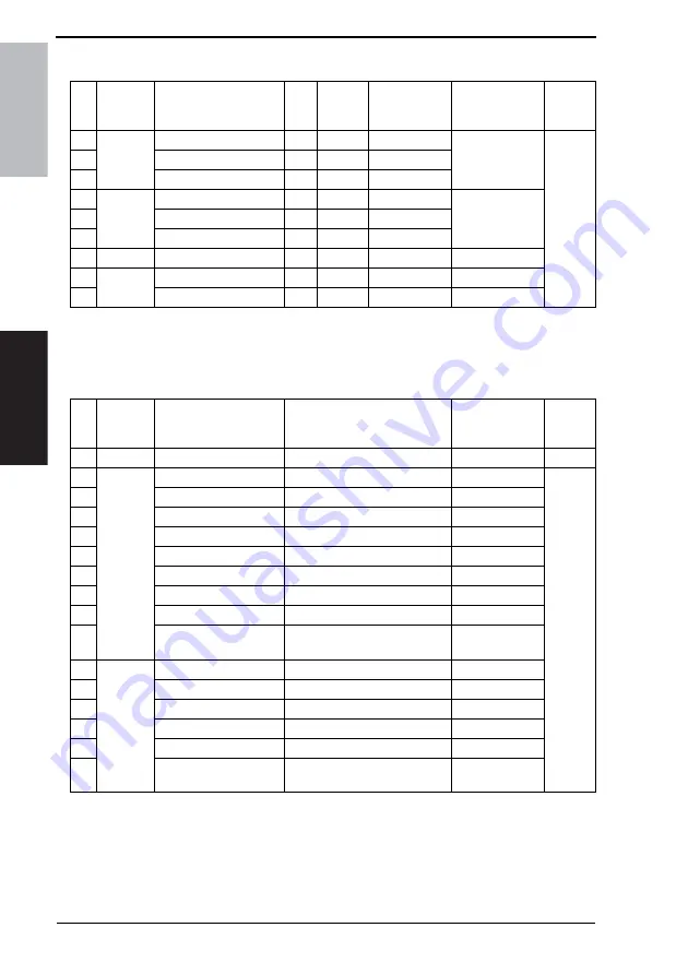
*1: Actual durable cycle is the Life counter value.
*2: ineo 210 only

3.1.2

Cleaning parts

*1: Actual cleaning cycle is the Life counter value.
*2: ineo 210 only

No.

Classifi-

cation

Parts name

Qua
ntity

Actual 

durable 

cycle *1

Pats No.

Descriptions

Ref.Page 

in this 

manual

1

DF-502

Pick-up Roller

1

120 K

4688-3032-XX Replace those 

three parts at the 
same time.

See 
each 
Option 
Service 
Manual.

2

Paper Take-up Roller

1

120 K

4688-3033-XX

3

Separation Roller

1

120 K

4688-3034-XX

4

DF-605 
*2

Pick-up Roller

2

200 K

4344-5003-XX Replace those 

three parts at the 
same time.

5

Paper Take-up Roller

1

200 K

4582-3014-XX

6

Separation Roller

1

200 K

4582-3047-XX

7

PF-502

Feed Roller

2

150 K

4686-3371-XX

8

MB-501

Paper Take-up Roller

1

150 K

4687-3012-XX

9

Separation Roller Assy

1

150 K

4034-0151-XX

No.

Classifi-

cation

Parts name

Actual cleaning cycle *1

Descriptions

Ref.Page 

in this 

manual

1

IR section Original Glass

80 K

19

2

DF-502

Pick-up Roller

30 K

See 
each 
Option 
Service 
Manual.

3

Paper Take-up Roller

30 K

4

Separation Roller

30 K

5

Registration Roller

30 K

6

Registration Roll

30 K

7

Exit Roller

30 K

8

Exit Roll

30 K

9

Transport Roll

30 K

10

Length Size Detection 
Sensor (PC7/AF)

30 K

11

DF-605 
*2

Pick-up Roller

50 K

12

Paper Take-up Roller

50 K

13

Separation Roller

50 K

14

Rollers and rolls

50 K

15

Scanning Guide

50 K

16

Reflective Sensor 
Section

50 K

Summary of Contents for ineo 161

Page 1: ...ineo 161 ineo 210 Dynamic balance www develop de Service Manual Field ...

Page 2: ......

Page 3: ...nts the number of times the revision has been made To indicate clearly a section revised show in the lower outside section of the correspond ing page A number within represents the number of times the revision has been made NOTE Revision marks shown in a page are restricted only to the latest ones with the old ones deleted When a page revised in Ver 2 0 has been changed in Ver 3 0 The revision mar...

Page 4: ......

Page 5: ...eplacing the Imaging Unit IU 11 3 3 4 Disassembly of the IU 12 3 3 5 Replacing the PC Drum 13 3 3 6 Replacing the Ozone Filter 14 3 3 7 Replacing the PC Drum Charge Corona Assy 14 3 3 8 Replacing the Cleaning Blade 14 3 3 9 Cleaning of the PC Drum Paper Separator Fingers 15 3 3 10 Cleaning of the Ds Collars 15 3 3 11 Cleaning of the Developer Scattering Prevention Plate 15 3 3 12 Replacing the Dev...

Page 6: ...age Unit HV1 35 6 3 5 Power Supply Unit PU1 35 6 3 6 Paper Size Detecting Board PWB I 36 6 3 7 Heater Relay Board PWB RY 200 V area only 37 6 3 8 Pre image Transfer Board PWB R2 37 6 3 9 Manual Bypass 38 6 3 10 Manual Bypass Duplex Unit 38 6 3 11 Toner Hopper Unit 38 6 3 12 PH Unit 39 6 3 13 Disassembly of the Fusing Unit 40 6 3 14 CCD Unit 43 6 3 15 Scanner Exposure Lamp and Inverter Board PU2 44...

Page 7: ...tment section 67 8 Utility Mode 68 8 1 Utility Mode function tree 68 8 2 Utility Mode function setting procedure 69 8 2 1 Procedure 69 8 2 2 Exiting 69 8 2 3 Changing the setting value in Utility Mode functions 69 8 3 Setting in the Utility Mode 69 8 3 1 MACHINE SETTING 69 8 3 2 PAPER SOURCE SETUP 70 8 3 3 USER MANAGEMENT 71 8 3 4 ADMIN MANAGEMENT 72 8 3 5 COPY SETTING 1 73 8 3 6 COPY SETTING 2 74...

Page 8: ...onal AD 504 CD Registration Adjustment ineo 210 only114 Troubleshooting 13 Introduction 115 13 1 Electrical Components Check Procedure 115 13 1 1 Sensor 115 13 1 2 Switch 116 13 1 3 Solenoid 116 13 1 4 Clutch 116 13 1 5 Motor 117 14 Jam Display 118 14 1 Misfeed Display 118 14 1 1 Display Resetting Procedure 118 14 2 Sensor layout 119 14 2 1 System Mounted with DF 502 PF 502 and MB 501 119 14 3 Sol...

Page 9: ... Motor Malfunction 137 15 3 4 C004E Power Supply Cooling Fan Motor Malfunction 138 15 3 5 C0070 Toner Replenishing Motor Malfunction 139 15 3 6 C0210 Abnormal Image Transfer Voltage 140 15 3 7 C0500 Warm up Failure 141 15 3 8 C0501 Warm up Failure 2 ineo 210 Only 141 15 3 9 C0510 Fusing Failure Abnormally Low Fusing Temperature 141 15 3 10 C0511 Fusing Failure Abnormally Low Fusing Temperature 2 i...

Page 10: ...ading Section Black spots 160 17 2 7 Image Reading Section Blank streaks or bands 161 17 2 8 Image Reading Section Uneven image density 162 17 2 9 Image Reading Section Gradation reproduction failure 163 17 2 10 Image Reading Section Periodically uneven image 164 17 2 11 Image Reading Section Moire 165 17 2 12 Printer Section Blank copy 166 17 2 13 Printer Section Black copy 167 17 2 14 Printer Se...

Page 11: ...3 3 2 Duplexing Document Feeder DF 605 11 Key Counter Kit 3 Original Cover Kit OC 504 1 12 32MB Memory EM 101 4 Job Separator JS 503 13 64MB Memory EM 102 5 Duplex Unit AD 504 14 Printer Controller IC 205 6 Multiple Bypass MB 501 15 Network Interface Card NC 502 7 Paper Feed Unit PF 502 2 16 Internet Fax Network Scan Kit SU 502 8 Copy Desk DK 701 3 17 Fax Kit FK 505 9 Copy Desk DK 702 3 18 Shiftin...

Page 12: ...ey Counter Kit 2 Original Cover Kit OC 504 1 10 32MB Memory EM 101 3 Job Separator JS 503 11 64MB Memory EM 102 4 Multiple Bypass MB 501 12 Printer Controller IC 205 5 Paper Feed Unit PF 502 2 13 Network Interface Card NC 502 6 Copy Desk DK 701 3 14 Internet Fax Network Scan Kit SU 502 7 Copy Desk DK 702 4 15 Fax Kit FK 505 8 Copy Table DK 703 4 16 Shifting Unit SF 501 Illustration none 4035T1E501...

Page 13: ...veloping System HMT System Charging System Comb Electrode 1 DC Negative Corona with Scorotron System Image Transfer System Roller Image Transfer Paper Separating System Paper Separator Fingers and Charge Neutralizing Plate Fusing System Heat Roller Paper Discharging System Charge Neutralizing Brush Max Original Size A3 Paper Feed Tray 1 Manual Bypass Type Plain Paper 60 to 90 g m2 Transparencies T...

Page 14: ... 14 14 12 Fixed Full Size 1 00 Reduction 0 81 0 70 0 50 0 25 Enlargement 1 15 1 41 2 00 4 00 Variable 0 25 to 4 00 in 0 01 increments Lens Through Lens Exposure Lamp Rare Gas Fluorescent Lamp Max Current Consumption full system 1250 W ineo 210 200 V area 1200 W ineo 210 120 V area 1050 W ineo 161 200 V area 1000 W ineo 161 120 V area Current Consumption full system 5 5 A ineo 210 200 V area 10 A i...

Page 15: ...eight 487 mm Copier Only Copier Mass 38 kg Printing Speed ineo 210 21 printed pages min A4 300 dpi 12 printed pages min A4 600 dpi ineo 161 16 printed pages min A4 300 dpi 12 printed pages min A4 600 dpi Memory Shared with the copier Interface IEEE 1284 parallel USB Revision 1 1 except for Windows 95 and Windows NT Printer Language GDI Font Windows Complying OS Windows XP SP1 or later Windows 2000...

Page 16: ... Max 297 mm width 1 000 mm Super Fine Max 297 mm width 900 mm Internet fax Enable when the optional Internet Fax Network Scan Kit SU 502 and Network Interface Card NC 502 are installed One touch dial 27 keys Speed dial 200 fax numbers Group dial 27 groups 50 destination group Program dial 4 keys No 24 27 Other dialing On hook dial Automatic redial Manual redial Chain dial Combination dial Transmis...

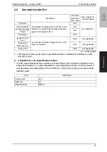
Page 17: ...127 V areas only 3 220 240 V areas only 4 European area No Classifi cation Parts name Qua ntity Actual durable cycle 1 Pats No Descriptions Ref Page in this manual 1 Paper take up section Feed Roller 1 150 K 4034 3012 XX 10 2 Separation Roller Assy 1 150 K 4034 0151 XX 10 3 Transport section Paper Dust Remover 1 40 K 4034 0756 XX 11 4 Imaging Unit section PC Drum 1 40 K 13 5 Ozone Filter 1 150 K 1...

Page 18: ... three parts at the same time 5 Paper Take up Roller 1 200 K 4582 3014 XX 6 Separation Roller 1 200 K 4582 3047 XX 7 PF 502 Feed Roller 2 150 K 4686 3371 XX 8 MB 501 Paper Take up Roller 1 150 K 4687 3012 XX 9 Separation Roller Assy 1 150 K 4034 0151 XX No Classifi cation Parts name Actual cleaning cycle 1 Descriptions Ref Page in this manual 1 IR section Original Glass 80 K 19 2 DF 502 Pick up Ro...

Page 19: ...de It may therefore vary depending on the conditions in which the copiers are used among different users Description Life value Specifica tion value New Copy Print Cycle Inhibited PC Drum The distance traveled by the PC Drum is con verted to a corresponding number of printed pages of A4 paper at 2P J 40 K Not inhibited 1 Cleaning Blade 40 K PC Drum Charge Corona 40 K Developer 40 K Image Transfer ...

Page 20: ...3 1 Replacing the Separation Roller Assy and Feed Roller 1 Slide out the Paper Feed Tray 1 2 Remove two screws and the mount ing bracket 3 Remove the Separation Roller Assy 4 Press down the Paper Lifting Plate 5 Snap off one C clip from the Feed Roller Assy 6 Slide the Feed Roller Assy to the rear and pull it off the Bearing at the front 7 Snap off one C clip and remove the Feed Roller 4035D001AB ...

Page 21: ... that remove the Toner Bottle and run ATDC Auto Adjust twice 103 1 Open the Front Door 2 Open the Right Door 3 Remove two screws and the IU Precautions for Installation of the IU When installing the IU use care not to damage the PC Drum Before attempting to install the IU be sure to fully open the Right Door Take care that if the IU is installed with the Right Door locked halfway it may interfere ...

Page 22: ...the rear of the IU and remove the harness cover 2 Remove two screws in the rear of the IU 3 Remove two screws at the front of the IU 4 Widen flaps on both ends marked with A in the photo on the left of the Drum Assy in the direction of the arrow and turn to take off the Devel oping Assy 4035D022AA 4035D023AA 4035D024AA 4035D025AA A A ...

Page 23: ...e Main Erase 3 3 5 Replacing the PC Drum 1 Remove two screws and the pivot shaft 2 Remove the PC Drum NOTE Protect the PC Drum that has been removed with a protective cloth If the PC Drum has been replaced with a new one apply a coat of toner to the surface of the new PC Drum 17 4035D026AA 4035D027AA 4035D028AA ...

Page 24: ...ction of the arrow to remove it from the side bracket 4 Slide out the PC Drum Charge Corona in the direction of the arrow 3 3 8 Replacing the Cleaning Blade 1 Remove the PC Drum Charge Corona Assy 2 Remove three screws and the Cleaning Blade NOTE When securing the Cleaning Blade tighten screws in the order of one on one edge one at the center and one on the other edge When the Cleaning Blade has b...

Page 25: ...wo Ds Collars clean of dirt 3 3 11 Cleaning of the Developer Scattering Prevention Plate 1 Remove three screws and the Devel oper Scattering Prevention Plate Precautions for Installation of the Developer Scattering Prevention Plate When securing the Developer Scat tering Prevention Plate tighten screws in the order of one on one edge one at the center and one on the other edge 2 Using a brush whis...

Page 26: ...his time could damage the Mylar for cleaning the ATDC Sensor Dump developer until almost no devel oper sticks to the Sleeve Roller 2 Pour one packet of developer NOTE Shake the packet of developer well before pouring When the developer has been changed make the ATDC AUTO ADJUST and enter the adjustment value on the Adjust Label 103 3 3 13 Cleaning of the Pre Image Transfer Guide Plate 1 Using a so...

Page 27: ... Assy to the Developing Assy to reconstruct the IU 7 Install the IU in the copier and run ATDC Auto Adjust of the Service mode 103 8 Enter the adjustment value on the Adjust Label 3 3 15 Application of Toner NOTE Perform these steps when the PC Drum and or Cleaning Blade have been replaced 1 With the IU divided into the Drum Assy and Developing Assy install the PC Positioning Jig in the rear of th...

Page 28: ...e arrow 3 3 16 Replacing the Image Transfer Roller Assy 1 Remove the Image Transfer Roller Assy NOTE Indentations or dirt on the surface of the Image Transfer Roller adversely affect the printed image Do not therefore touch or dirty with toner the surface of the Image Transfer Roller When handling the Image Transfer Roller hold onto the shaft or Bear ings of the roller Do not place a new Image Tra...

Page 29: ...Remove four screws and the Fusing Unit NOTE When removing the Fusing Unit make sure of the correct type of screws that must be removed NOTE When removing the Fusing Unit take care not to confuse the types of screw 3 3 18 Cleaning of the Original Glass and Original Scanning Glass 1 Using a soft cloth dampened with alcohol wipe the Original Glass and Original Scanning Glass clean of dirt 4035D045AA ...

Page 30: ... name Shape Parts No Personnel Remarks Scanner Mirrors Carriage Positioning Jigs 4034 7901 XX 4034 7902 XX 1 for each Ds Collar Positioning Jigs 4021 7903 XX 2 Db Gap Adjusting Jigs 4021 7904 XX 2 PC Positioning Jig 4021 4362 XX 2 Gauge 1144 7910 XX 2 4034F2C501DA 4034F2C502DA 4034F2C503DA 4034F2C504DA 4034F2C505DA ...

Page 31: ...is location in the search and then click Browse 6 Specify name of any given language WinXP in the folder in which the TWAIN driver is stored and then click OK 7 Click Next and then Finish 8 The Found New Hardware Wizard dialog box will appear again Repeat steps 4 7 to install all drivers For Windows 2000 1 Prepare the files necessary for upgrading the firmware and copy them to PC 2 Start the host ...

Page 32: ... of the driver Advanced and then click Next With Windows 98 click Next Then in the dialog box that will then appear choose Search for the best driver for your device recommended and then click Next 6 Choose Specify a location and then click Browse 7 Specify name of any given language Win9X in the folder in which the TWAIN driver is stored and then click OK 8 Click Next Then continue following the ...

Page 33: ...able Wait until the hardware is detected 5 Open Properties of My Computer Then select System Properties Hardware Device Manager Imaging devices to check that the XXXXXXXXXXX Model Name icon has been added 6 Double click the Update file in the Update Software folder The A3S A4S Update F W VXXX screen will appear 7 Click the Browse button Then select the Update file that has been copied onto drive C...

Page 34: ...TE NEVER turn OFF and ON the Power Switch as long as the above screens are being displayed 10 When the following message appears in the Display it indicates that upgrading of the firmware has been completed 11 Click the OK button to quit A3S A4S Update F W VXXX 12 Turn OFF and ON the Power Switch of the copier 4035D530CA PWB C C 4980D051AB 4035D532AA ...

Page 35: ...perly To perform this procedure you need the Fax board BIOS ROMs U17 U19 and the TWAIN Driver dedicated to this specific purpose 1 Turn off the power switch of copier 2 Disconnect the USB cable from the copier and host computer 3 Remove the rear cover 31 4 Disconnect jumper CJ1 on the Control board PWB C C from 1 2 and connect it to 2 3 5 Disconnect jumper FJ1 on the Fax board from 1 2 and connect...

Page 36: ...owing message will appear on message panel and copier waits for file data 10 Perform steps 4 12 in the firmware upgrading procedure to upgrade the firmware 11 Turn power off 12 Remove the Fax board 13 Disconnect jumper CJ1 on the Control board PWB C C from 2 3 and connect it to 1 2 14 Disconnect jumper FJ1 on the Fax board from 2 3 and connect it to 1 2 15 Connect jumper FJ2 to 1 2 on the Fax boar...

Page 37: ...ms in operation manual and make necessary adjustment Note that when two or more screws are used on the part in questions only one representative screw may be marked with red paint C Variable Resistors on Board NOTE Do not turn the variable resistors on boards for which no adjusting instructions are given in Adjustment Setting D Removal of PWBs NOTES When removing a circuit board or other electrica...

Page 38: ...Field Service Ver 1 0 Apr 2005 28 ineo 161 ineo 210 Maintenance E Other Screws not Marked with Red Paint 1 PH Unit Section 2 IR Unit Section PH Unit PH Unit Base Plate 4035D137AA Left Side Right Side 4035D136AA ...

Page 39: ...over 31 11 Original Scanning Glass 31 12 Right Rear Cover 31 13 Left Rear Cover 31 14 Upper Rear Cover 31 15 Rear Cover 31 16 Rear Right Cover 31 17 Right Cover 31 18 Board and etc Master Board 33 19 Control Board 33 20 High Voltage Unit 35 21 Power Supply Unit 35 22 Paper Size Detecting Board 36 23 Heater Relay Board 37 24 Pre image Transfer Board 37 25 Unit Manual Bypass 38 26 Manual Bypass Dupl...

Page 40: ...paration Roller 60 42 Feed Roller 60 43 Upper Lower Synchronizing Rollers 60 44 Paper Dust Remover 61 45 Bypass Transport Roller Roll 61 No Section Part name Ref Page No Section Part name Ref Page 1 IU PC Drum Paper Separator Fingers 15 2 Ds Collars 15 3 Developer Scattering Prevention Plate 15 4 Pre Image Transfer Guide Plate 16 5 IR Mirrors 62 6 Lens 62 7 CCD Sensor 62 8 Scanner Rails Bearings 6...

Page 41: ...e Front Door Remove six screws Remove the Front Cover 5 Paper Exit Cover Remove the Front Cover Remove one screw Remove the Paper Exit Cover 6 Front Door Open the Front Door Snap off one C clip Slide the Front Door to the right and pull it off 7 Tray 1 Slide out Tray 1 Remove two screws Remove the fixing brackets on the right and left ends of Tray 1 Remove Tray 1 8 Left Cover Remove the Front Cove...

Page 42: ... Remove the Left Rear Cover 14 Upper Rear Cover Remove four screws Remove the Upper Rear Cover 15 Rear Cover Remove nine screws Remove the Rear Cover NOTE When the Rear Cover is to be installed make sure of type of screw 9735 0306 14 8 Screw 9770 0308 14 1 Screw 16 Rear Right Cover Remove two screws Remove the Rear Right Cover 17 Right Cover Remove the Upper Rear Cover Remove the Front Cover Remov...

Page 43: ...1 2 Unplug all connectors from the Mas ter Board 3 Remove four screws and the Master Board 6 3 3 Control Board PWB C C 1 Remove the Rear Cover and Upper Rear Cover 31 2 Remove the Master Board 33 3 Unplug all connectors from the Con trol Board 4 Remove two screws and two hold ers 4035D049AA 4035D050AA 4035D051AB 4035D052AA ...

Page 44: ...l Board When the Control Board PWB C C is replaced with a new one Parameter Chip U16 must be demounted from the old PWB C C and remounted on the new PWB C C Mount the Parameter Chip U16 of the old PWB C C on the new PWB C C NOTE Note the alignment notch marked with A on the Parameter Chip U16 when mounting the IC 4035D053AB 4035D514AA 1171D049AA ...

Page 45: ... connectors from the High Voltage Unit 4 Remove two screws and the High Voltage Unit 6 3 5 Power Supply Unit PU1 1 Remove the Left Cover Rear Cover and Upper Rear Cover 31 2 Remove the Master Board 3 Remove the Control Board 33 4 Remove the harness from four wiring saddles and one edge cover 5 Remove four screws and protective cover 1 4035D054AA 4035D055AA 4035D522AA ...

Page 46: ...protective cover 2 7 Unplug all connectors from the Power Supply Unit 8 Remove six screws and the Power Supply Unit 6 3 6 Paper Size Detecting Board PWB I 1 Remove the Rear Cover 31 2 Slide out the Paper Feed Tray 1 3 Unhook two tabs and remove the holder 4035D056AB 4035D057AB 4035D523AA 4035D058AA ...

Page 47: ...etecting Board 6 3 7 Heater Relay Board PWB RY 200 V area only 1 Remove the Front Cover and Left Cover 31 2 Unplug two connectors and remove three PWB supports and the Heater Relay Board 6 3 8 Pre image Transfer Board PWB R2 1 Open the Right Door 2 Remove two screws and the Pre image Transfer Board 4035D059AA 4035D060AA 4035D139AB 4035D061AA ...

Page 48: ...tor and remove the Manual Bypass 6 3 10 Manual Bypass Duplex Unit 1 Remove the Rear Right Cover 31 2 Open the Right Door 3 Remove two screws unplug one connector and remove the Manual Bypass 6 3 11 Toner Hopper Unit 1 Remove the Front Door Front Cover Left Cover and Paper Exit Tray 31 2 Remove the Toner Bottle 3 Remove three screws and the unit cover 4532D008AC 4035D143AA 4035D062AA ...

Page 49: ...5 Remove the Toner Hopper Unit 6 Remove two screws and the Toner Replenishing Motor 6 3 12 PH Unit 1 Remove the Front Cover Left Cover Rear Cover Paper Exit Tray and Rear Inside Cover 31 2 Disconnect one flat cable and one connector from the Master Board 4035D063AA 4035D064AA 4035D065AA 4035D066AA ...

Page 50: ...e 4 Remove the harness from one wiring saddle 5 Remove three screws with springs and the PH Unit 6 3 13 Disassembly of the Fusing Unit A Removal of the Thermistor and Paper Separator Fingers 1 Remove the Fusing Unit 19 2 Remove the pressure springs on both ends of the unit 4035D067AA 4035D068AA 4035D069AA 4035D070AA ...

Page 51: ...able Guide Assy 4 Remove four shoulder screws two washers and the Fusing Roller rt Cover 5 Remove two Bearings and the Fus ing Roller rt Precautions for Installation of the Fusing Roller rt Install the right and left Bearings in the directions shown in the photo on the left 4035D145AA 4035D071AB 4035D142AA 4035D521AA ...

Page 52: ... 210 Maintenance 6 Remove one screw Then slide the Paper Separator Finger Assy in the direction of the arrow and take it off 7 Remove one screw and the Ther mistor 8 Unhook springs and remove the four Paper Separator Fingers 4035D072AA 4035D073AA 4035D074AA ...

Page 53: ...ove four screws and the CCD Unit Cover 3 Mark a line along the profile of the CCD Unit mounting bracket as shown on the left 4 Unplug one connector 5 Remove three screws to which green paint has been applied and the CCD Unit NOTE When removing the CCD Unit loosen or remove only these speci fied screws 4035D016AA 4035D075AA 4035D076AA 4035D077AA ...

Page 54: ... 15 Scanner Exposure Lamp and Inverter Board PU2 1 Remove the Original Glass and Original Scanning Glass 31 2 Remove two screws to which no red paint has been applied Then remove the Scan ner Assy from the Scanner Drive Cables NOTE Removal of the Scanner Assy leaves the front and rear Scanner Drive Cables attached with the fixing brackets 3 Remove one screw and the cable holder 4 Remove one flat c...

Page 55: ...ug one connector and remove the Inverter Board 6 Remove two screws and the Expo sure Lamp 6 3 16 Scanner Motor 1 Remove the Right Rear Cover 31 2 Remove the Scanner Motor harness from the five wiring saddles 3 Unplug one connector from the Con trol Board 4035D081AA 4035D082AA 4035D083AA 4035D084AA ...

Page 56: ... Drive Cables A Removal Procedure 1 Remove the Left Cover Front Cover Rear Cover Upper Rear Cover Right Rear Cover Original Glass and Original Scanning Glass 31 2 Loosen two screws to which red paint has been applied and remove the Scanner Assy NOTE Loosen the two red painted screws to remove the Scanner Assy in this step which differs from the removal procedure for the Scanner Assy as a single un...

Page 57: ... Maintenance 3 Unhook the springs from the cable hooks at the front and rear 4 Remove the front cable from the cable pulley 5 Remove the rear cable from the cable pulley 6 Remove one screw from the front cable pulley 4035D087AB 4035D088AA 4035D089AA 4035D090AA ...

Page 58: ...Maintenance 7 Remove one screw from the rear cable pulley 8 Snap off one C ring from the front side of the Pulley Assy 9 Snap off one C ring from the rear side of the Pulley Assy 10 Pull out the shaft and two Bearings 4035D091AA 4035D092AA 4035D093AA 4035D094AB ...

Page 59: ...le pulley B Reinstallation Procedure Overall View NOTE The cables are color coded and differ in type from each other the front cable is sil ver while the rear cable is black Make sure that no part of the cable rides on the other 1 Pass the cable black through wire pulley 2 4035D095AA 4035D109AA Pulley A Pulley B Pulley C Pulley D Wire pulley 2 Wire pulley 1 4035D110AA Side B Side A ...

Page 60: ...rting with the slit at the bot tom in the rear left of the pulley 3 Wind the cable on side A around wire pulley 2 four turns clockwise starting with the slit at the top in the front left of the pulley 4 Affix tape to secure the cable to wire pulley 2 5 Pass the cable silver through wire pulley 1 4035D111AA 4035D112AA 4035D113AA 4035D114AA Side B Side A ...

Page 61: ...kwise starting with the slit at the top in the rear left of the pulley 8 Affix tape to secure the cable to wire pulley 1 9 Use the two screws to secure the gear to wire pulley 2 NOTE Make sure that the cable pulley is doweled to the gear 10 Mount the front and rear cable pulleys onto the shaft and install the shaft to the copier NOTE Install the shaft as shown on the left 11 Fit two Bearings and s...

Page 62: ... the screw is installed differs between the front and rear Note the correct direction 13 Wind the lower cable of wire pulley 1 around pulley A 14 Wind the cable from pulley A around pulley B NOTE Wind the cable around the outer groove in pulley B 15 Pass the cable from pulley B into the hole in the IR frame 4035D118AA 4035D119AA Pulley A 4035D120AA Pulley A Pulley B 4035D121AA ...

Page 63: ...y D NOTE Wind the cable around the outer groove in pulley D 18 Pass the cable from pulley D into the hole in the IR frame 19 Pass the leading edge of each of the front and rear cables into the space between the IR frame and copier frame 20 Affix tape to temporarily secure the cables to the copier frame 4035D124AA Pulley C 4035D125AA Pulley C Pulley D 4035D126AA 4035D122AA ...

Page 64: ...groove in pulley D 23 Peel off the pieces of tape that secure the front and rear cable pul leys 24 Peel off the tape used to temporarily secure the cables to the copier frame Hook a spring to the leading edges of the front and rear cables 25 Temporarily secure the Scanner to the front and rear cables 26 Adjust the position of the Scanner and the 2nd 3rd Mirrors Carriage 110 6 3 18 Main Motor 1 Rem...

Page 65: ...the Control Board 33 4 Remove nine screws and the protec tive cover 5 Remove two screws unplug one connector and remove the Power Unit Cooling Fan Motor 6 3 20 Fusing Cooling Fan Motor 1 Remove the Rear Right Cover 31 2 Open the Right Door 3 Remove the Image Transfer Roller Assy 18 4 Remove one screw and the Transport Unit Assy NOTE Use care not to lose the two springs 4035D524AA 4035D097AB 4035D0...

Page 66: ...d the Duct Assy 6 Remove seven screws and the mounting bracket 7 Remove two screws unplug one connector and remove the Fusing Cooling Fan Motor 6 3 21 Paper Size Sensor Assy 1 Remove the Rear Cover 31 2 Slide out the Paper Feed Tray 1 3 Remove one screw 4035D099AC 4035D100AB 4035D101AA 4035D102AA ...

Page 67: ... Switch 1 Remove the Rear Cover 31 2 Remove the harness from one wiring saddle 3 Remove two screws to which red paint has been applied 4 Unplug four connectors and remove the Fusing Unit Interlock Switch Assy NOTE When installing the Fusing Unit Interlock Switch Assy make sure that the connectors are connected properly 4035D103AA 4035D130AC 4035D131AA 4035D132AA ...

Page 68: ...the gauge between the projection of lever and the top surface of Fusing Unit Interlock Switch and then secure the switch holder so that the gap is 0 5 mm NOTE Use the 0 5 mm thick portion of gauge Insert the gauge between the rear side projection of lever and the top surface of Fusing Unit Interlock Switch for ineo 161 5 Close the right door and then use a tester to make sure that the Fusing Unit ...

Page 69: ...ng between 2A and 2B 3A and 3B NOTE If there is any abnormality in conducting check repeat adjustment again from step 4 6 3 23 Inch Metric Sensor 1 Assy 3rd area Only 1 Remove the Rear Cover 31 2 Remove one screw unplug one con nector and remove the Inch Metric Sensor 1 Assy 6 3 24 Flickerless Resistor Only for 200 V area of ineo 161 1 Remove the Rear Cover 31 2 Remove the Master Board 33 3 Remove...

Page 70: ...2 Using a soft cloth dampened with alcohol wipe the Separation Roller clean of dirt 6 4 2 Feed Roller 1 Remove the Separation Roller Assy 2 Using a soft cloth dampened with alcohol wipe the Feed Roller clean of dirt 6 4 3 Upper Lower Synchronizing Rollers 1 Open the Right Door 2 Remove the Imaging Unit 11 3 Using a soft cloth dampened with alcohol wipe the Upper and Lower Synchronizing Rollers cle...

Page 71: ...mover 6 4 5 Bypass Transport Roller Roll 1 Remove the Rear Right Cover 31 2 Open the Right Door 3 Remove two screws unplug one connector and remove the Manual Bypass Assy 4 Using a soft cloth dampened with alcohol wipe the Bypass Transport Roller clean of dirt 5 Using a soft cloth dampened with alcohol wipe the Bypass Transport Roll clean of dirt 4035D009AA 4532D008AC 4035D011AB 4532D015AA ...

Page 72: ...ohol wipe the mirrors clean of dirt 6 4 7 Lens 1 Remove the Original Glass 31 2 Using a soft cloth dampened with alcohol wipe the Lens clean of dirt 6 4 8 CCD Sensor 1 Remove the Original Glass 31 2 Remove four screws and the CCD Unit Cover 3 Pulling the tabs on both sides of the Lens Cover remove the Lens Cover 4035D014AB 4035D015AA 4035D016AA 4035D017AA ...

Page 73: ...rings clean of dirt NOTE After the Scanner rails and Bear ings have been cleaned apply oil copier lubricant A or FLOIL 947P 6 4 10 PH Window 1 Remove the Front Cover Left Cover and Exit Tray 31 2 Using a soft cloth dampened with alcohol wipe the PH window clean of dirt 6 4 11 Pre Image Transfer Lower Guide Plate 1 Open the Right Door 2 Using a soft cloth dampened with alcohol wipe the Pre image Tr...

Page 74: ...f dirt NOTE Use care not to allow the Image Transfer Roller to be touched with alcohol Do not allow the soft cloth to be caught by the tip of the Charge Neu tralizing Plate 6 5 Option counter 6 5 1 Installation of the Key Counter 1 Cut out the knockout from the Right Cover 2 Using two screws secure the counter mounting bracket 3 Connect the Key Counter Socket connector 4035D044AB 4623D001AA 4623D0...

Page 75: ...tenance 4 Using two screws secure the Key Counter Socket 5 Using two screws secure the Key Counter cover 6 Plug in the Key Counter NOTE When the Key Counter is mounted set Machine Counter Copying of the Security mode to Disabled 109 4623D004AA 4623D005AA 4623D006AA ...

Page 76: ...6 Other Field Service Ver 1 0 Apr 2005 66 ineo 161 ineo 210 Maintenance Blank page ...

Page 77: ...ht ventilation etc levelness of the installation site 5 The original has a problem that may cause a defective image 6 The density is properly selected 7 The Original Glass slit glass or related part is dirty 8 Correct paper is being used for printing 9 The units parts and supplies used for printing developer PC Drum etc are properly replenished and replaced when they reach the end of their useful ...

Page 78: ...K 6 PRINT DENSITY 7 LCD CONTRAST 8 LANGUAGE MACHINE SETTING 1 INCH METRIC 2 TRAY1 PAPER 3 PAPER TYPE PAPER SOURCE SETUP 1 DRUM DEHUMIDIFY 2 TONER REPLENISHER USER MANAGEMENT ADMIN MANAGEMENT 1 AUTO SHUT OFF 2 COPY TRACK COPY SETTING 1 1 PAPER PRIORITY 2 DENSITY PRIORITY 3 DENSITY LEVEL A 4 DENSITY LEVEL M 5 BINDING POS 6 MARGIN SETTING 7 ERASE SETTING 8 SMALL ORIGINAL COPY SETTING 2 1 MIXED ORIGIN...

Page 79: ...nt A AUTO PANEL RESET B ENERGY SAVE MODE C AUTO SHUT OFF Purpose Use To set the time it takes the Auto Panel Reset function which resets the panel settings when the set period of time elapses after a copy cycle has been completed or the last key operated to be activated Setting Procedure The default setting is 1 min OFF ON 0 5 1 2 3 4 5 Purpose Use To set the time it takes the copier to enter the ...

Page 80: ...t the reading image density level when the Original Glass is used Setting Procedure The default setting is MODE1 MODE1 To produce a copy having an image density equivalent to that of the original MODE2 To lower the image density to prevent a dirty copy from being produced Purpose Use To set the print density Setting Procedure The default setting is 0 Setting range 2 LIGHT to 2 DARK Purpose Use To ...

Page 81: ...ult of a sudden change in temperature or an increased humidity Setting Procedure Step 1 Select DRUM DEHUMIDIFY and press the Yes key 2 The drum dry sequence is automatically terminated after the lapse of a predeter mined period of time and the initial screen reappears Purpose Use To forcedly replenish the supply of toner when ID drops as a result of a reduced T C ratio after a large number of copi...

Page 82: ...d for the copy track function or to change or delete a previously set access number Setting Procedure Registration Procedure 1 Type any access number from the 10 Key Pad 2 Press the Yes key to validate the entry of the access number 3 To continue registering access numbers repeat steps 1 and 2 Up to 20 different accounts can be set 4 When the registration procedure is completed quit the function b...

Page 83: ...y 4 Press the No key to clear the count value 5 When the count value has been cleared quit the function by pressing the Yes key All Clear Procedure 1 Select CLEAR and press the Yes key 2 When you are prompted to confirm if all count values are to be cleared press the Yes key Purpose Use To set the priority paper source Setting Procedure The default setting is 1ST 1ST 2ND 3RD 4TH 5TH BYPASS Purpose...

Page 84: ...set the erase width when making erase copies Setting Procedure The default setting is LEFT and 10 mm Step 1 Select the erase position LEFT UPPER FRAME 2 Set the erase width Setting range 5 to 20 mm Purpose Use To set whether to enable or disable copying when an original of a size smaller than the detectable one is loaded in the Auto Paper mode Setting Procedure The default setting is DISABLE DISAB...

Page 85: ...ion either Non Sort Sort or Group Setting Procedure The default setting is NON NON SORT GROUP Purpose Use To set the layout of copy images in 4in1 copies Setting Procedure The default setting is PATTERN1 4035S501AA PATTERN1 PATTERN2 4035S502AA Purpose Use To select the crisscross function Setting Procedure The default setting is ON ON OFF Purpose Use To select whether to enable or disable 2 sided ...

Page 86: ...ge Erase 4 Vertical Edge Erase 5 Loop Adjust Tray1 6 3 3 Fuser Temp 7 CCD APS Size 8 Adjust PRN Main Regist 9 PRN Sub Regist 10 CCD Main Zoom 11 CCD Sub Zoom 12 CCD Main Regist 13 CCD Sub Regist 14 ADF Sub Zoom 15 ADF Main Regist 16 ADF Sub Regist 1 17 ADF Sub Regist 2 18 Clear Data PM Counter 19 1 1 1 Supplies Life Count 20 2 2 3 2 Function Paper Feed Test 21 2 2 ATDC Auto Adjust 22 1 4 Print Tes...

Page 87: ... Board Replace ATDC Sensor Replace PH Memory Clear Install Scanner Drive Cable Add Original Size Sensor DF 605 DF 502 PF 502 MB 501 Replace Pick Up Roller Replace Take Up Roller Replace Separator Roller Replace Pick Up Roller Replace Take Up Roller Replace Separator Roller Replace Take Up Roller Replace Take Up Roller Replace Separator Roller Assy 1 4 2 3 11 4 12 5 13 6 3 3 3 7 2 8 1 9 1 10 2 11 2...

Page 88: ... been executed re enter those data The following data of Adjust are indicated at the factory on the Adjust Label located inside the Front Door The other side of the Toner Replacement Label PRN Main Regist PRN Sub Regist CCD Main Zoom CCD Sub Zoom CCD Main Regist CCD Sub Regist The ATDC value at the time of setting up of the PC Drum Unit is also entered on the Adjust Label at installation The setti...

Page 89: ...procedure to enter the Service mode 10 1 1 Procedure 1 Press the Utility key 2 Press the following keys in this order 3 Stop 0 0 Stop 0 1 4 The Service mode menu screen will appear 10 1 2 Exiting Press the Panel Reset key as many times as it is required to display the initial screen 10 1 3 Changing the Setting Value in Service Mode Functions 1 Select the desired item using key 2 Select the setting...

Page 90: ...d PLAIN FUSER TEMP Ad THICK FUSER TEMP Ad OHP LEADING EDGE ERASE TRAILING EDGE ERASE VERTICAL EDGE ERASE LOOP ADJUST TRAY1 LOOP ADJUST TRAY2 TO TRAY5 LOOP ADJUST DUPLEX LOOP ADJUST BYPASS FLS PAPER SIZE CCD APS SIZE GDI TIMEOUT 1 SERVICE S CHOICE PRN MAIN REGIST PRN SUB REGIST CCD MAIN ZOOM CCD SUB ZOOM CCD MAIN REGIST CCD SUB REGIST ADF SUB ZOOM ADF MAIN REGIST ADF SUB REGIST1 ADF SUB REGIST2 ADF...

Page 91: ...NTER SCAN COUNTER PAPER SIZE COUNTER MISFEED COUNTER TROUBLE COUNTER TONER DENSITY LEVEL PROCESS CONTROL MAIN F W VER ENGINE F W VER PCL F W VER NIC F W VER ADF F W VER MAIN RAM SIZE PCL RAM SIZE SERIAL NO CUSTOMER ID 4 DISPLAY PAPER FEED TEST PROCESS CHECK ATDC AUTO ADJUST PRINT TEST PATTERN ADF FEED TEST COPY ADF GLASS AREA CCD MOVE TO HOME SCAN TEST ADF WIDTH ADJ MAX ADF WIDTH ADJ MIN ADF SENSO...

Page 92: ...ION1 EXPANSION1 EXPANSION2 7 FIXED ZOOM CHANGE 8 FACTORY TEST PANEL BUZZER TEST RAM TEST 9 CLEAR DATA MEMORY CLEAR PM COUNTER MAINTENANCE COUNTER SUPPLIES LIFE COUNT APPLICATION COUNTER SCAN COUNTER PAPER SIZE COUNTER MISFEED COUNTER TROUBLE COUNTER ADF BACKUP CLEAR TOTAL COUNTER COUNT SIZE COUNTER COUNT PLUG IN COUNTER COPY MACHINE COUNTER 10 SECURITY ...

Page 93: ...ng Procedure The default setting is 0 0 Not counted 1 Counted The maintenance call display is given when the counter reaches 0 2 Counted The Tech Rep call display is given and the initiation of any new copy cycle is inhibited when the counter reaches 0 When 1 or 2 is selected a screen will then appear to allow the counter value to be entered NOTE The counter value is decremented until it reaches 9...

Page 94: ...id Decrease the setting value to eliminate fog Setting range 2 to 2 Purpose Use To set the temperature of the Fusing Roller for each type of paper thereby making up for fusing performance that changes with the operating environment or type of paper When fusing failure occurs When the type of paper is changed Setting Procedure The default setting is 0 Setting range 1 to 2 Setting value Paper width ...

Page 95: ... C 220 mm or less 1 221 mm or more 170 C 220 mm or less Purpose Use To set the fusing temperature when thick paper is used When fusing failure occurs Setting Procedure The default setting is 0 Setting range 1 to 1 Setting value Paper width Mode selected in Service s Choice Mode 1 Mode 3 CD Fusing Heater Lamp temperature 1 251 mm or more 210 C 200 C 250 mm or less 210 C 200 C 0 default value 251 mm...

Page 96: ...etting Procedure The default setting is 0 Setting range 1 to 1 Setting value Paper width Mode selected in Service s Choice Mode 1 Mode 3 CD Fusing Heater Lamp temperature 1 251 mm or more 180 C 175 C 250 mm or less 165 C 165 C 0 default value 251 mm or more 180 C 165 C 250 mm or less 155 C 155 C 1 251 mm or more 170 C 155 C 250 mm or less 145 C 145 C Setting value Mode selected in Service s Choice...

Page 97: ...in step 3 Adjustment Instructions To make the erase width smaller decrease the setting value To make the erase width greater increase the setting value 4035D516AA A Purpose Use To adjust the erase width on the trailing edge of the image by varying the laser emission timing When the PH Unit has been replaced Setting Procedure The default setting is 4 mm 0 mm 1 mm 2 mm 3 mm 4 mm 5 mm Adjustment Proc...

Page 98: ...greater increase the setting value C 4035D518AA C Purpose Use To adjust the length of the loop formed in the paper before the Synchronizing Roller When a skew feed fold or misfeed of paper occurs When variations in the amount of void on the leading edge occurs Setting Procedure Setting range 3 9 to 3 9 mm 1 step 0 6 mm Adjustment Procedure 1 Call Service s Choice of Service Mode to the screen 2 Se...

Page 99: ...3 9 to 3 9 mm 1 step 0 6 mm Adjustment Procedure 1 Call Service s Choice of Service Mode to the screen 2 Select Loop Adjust Bypass and press the Yes key 3 Using key select the desired setting value 4 Press the Yes key to validate the setting value selected in step 3 Adjustment Instructions Try a different setting value until there are no variations in the amount of void on the leading edge and pap...

Page 100: ...e paper 2 Enter Function of the Service mode 3 Select Print Test Pattern and then Test Pattern1 Then press the Start key This will produce a test pattern 4 Check to see if width A on the test pattern falls within the specified range If width A falls outside the specified range perform the following steps to make an adjustment 5 Select Adjust of PRN Main Regist 6 Using key select the appropriate se...

Page 101: ...2 Enter Function of the Service mode 3 Select Print Test Pattern and then Test Pattern1 Then press the Start key This will produce a test pattern 4 Check to see if width B on the test pattern falls within the specified range If width B falls outside the specified range perform the following steps to make an adjustment 5 Select Adjust of PRN Sub Regist 6 Using key select the appropriate setting val...

Page 102: ...length of the scale is 200 mm Zoom Ratio Specifications Zoom Ratio Full size 1 00 Specifications 200 2 0 mm 1 Place a scale on the Original Glass in parallel with the Original Width Scale and make a copy 2 Measure the length of the scale on the copy If the amount of error falls outside the specified range perform the following steps to make an adjustment 3 Enter Adjust of the Service mode 4 Select...

Page 103: ...e is 300 mm Zoom Ratio Specifications Zoom Ratio Full size 1 00 Specifications 300 3 0 mm 1 Place a scale so that it is at right angles to the original width scale and copy it 2 Measure the length of the scale on the copy If the amount of error falls outside the specified range perform the following steps to make an adjustment 3 Enter Adjust of the Service mode 4 Select Adjust of CCD Sub Zoom 5 Us...

Page 104: ...ications 0 2 0 mm 1 Load the Paper Feed Tray 1 with A4 crosswise paper 2 Enter Function of the Service mode 3 Select Print Test Pattern and then Test Pattern1 Then press the Start key This will produce a test pattern 4 Place the test pattern produced in step 3 on the Original Glass and make a copy of it 5 Place the test pattern original on top of the copy and check for deviation in width A If the ...

Page 105: ...n of the Service mode 3 Select Print Test Pattern and then Test Pattern1 Then press the Start key This will produce a test pattern 4 Place the test pattern produced in step 3 on the Original Glass and make a copy of it 5 Place the test pattern original on top of the copy and check for deviation in width B If the deviation in width B falls outside the specified range perform the following steps to ...

Page 106: ... option service manual DF 502 DF 605 for details Function Test Copy Adjust Purpose Use To adjust variations in machining and installation accuracy of different parts by varying the scanning start position in the sub scanning direction when the Automatic Document Feeder is used NOTE This adjustment should be made after the ADF Sub Zoom adjustment Setting Procedure Refer to the option service manual...

Page 107: ...er to the option service manual DF 605 for details Purpose Use To manually adjust the ATDC Sensor voltage Setting Procedure The default setting is 155 Setting range 123 to 186 The adjusted value of the ATDC Auto Adjust is the setting value Purpose Use NOTE Never change this setting If it is changed the Tech Rep call C03FF will appear Setting Procedure Default setting depend on the marketing area s...

Page 108: ... Rep call will appear according to the setting on maintenance counter of service choice 83 Setting Procedure To clear the count use Clear Data of the Service mode Purpose Use To display the count of the Supplies Life Counter When the counter reaches 0 life 1 will be detected and maintenance call M2 will appear The initial value is 40000 and the countdown system is used Setting Procedure To clear t...

Page 109: ...AL 11 LETTER L 12 LETTER C 13 INVOICE 14 OTHER 15 PLAIN PAPER 16 RECYCLE PAPER 17 SPECIAL PAPER 18 1 SIDE PAPER should not be used only for ineo 161 19 OHP 20 THICK PAPER 21 ENVELOPE To clear the count use Clear Data of the Service mode Purpose Use To display the count of the number of paper misfeeds that have occurred at different parts of the copier Setting Procedure 1 BYPASS 2 TRAY1 3 TRAY2 4 T...

Page 110: ...0510 Fusing failure abnormally low temperature C0511 Fusing failure abnormally low temperature 2 should not be used only for ineo 210 C0520 Fusing failure abnormally high temperature C0521 Fusing failure abnormally high temperature 2 should not be used only for ineo 210 C0650 Faulty Scanner Home Position Sensor C0B60 Bin Switching Motor malfunction C0B80 Shift Motor malfunction C0F32 Faulty ATDC S...

Page 111: ... C ratio when the image density is defective Display T C 80 8 0 8 4 100 10 0 10 4 130 13 0 13 4 135 13 5 13 9 140 14 0 14 4 145 14 5 14 9 Purpose Use To display the Vg and Vb values Display Vb V Vg V 5 300 450 0 400 550 5 500 650 Purpose Use To display the main firmware version information Purpose Use To display the engine firmware version information Purpose Use To display the PCL firmware versio...

Page 112: ...o display the serial number of the copier Purpose Use To display the customer ID of the copier Purpose Use To check for correct paper passage of the paper take up and transport system by let ting the copier consecutively take up and feed paper without involving actual printing action Here are the details of operation involved in the paper passage motion The Scanner does not make any scan motion Pa...

Page 113: ...rn Purpose Use To produce halftone and gradation test patterns When checking for uneven density or uneven pitch When checking for gradation reproducibility Setting Procedure Step 1 Select the paper source TRAY1 TRAY2 2 Select the type of test pattern 3 Press the Start key to let the copier produce the test pattern Purpose Use To check for correct paper passage of the paper take up and transport sy...

Page 114: ...xposure Lamp turns ON properly and the Scanner moves properly When the scan motion is faulty Setting Procedure Step 1 Press the Start key to start the scan test Pressing the Stop key will stop the scan test Purpose Use To adjust the Original size detection VR When PBA VR board is replace When PBA CONT board is replace Setting Procedure Refer to the option service manual DF 605 for details Purpose ...

Page 115: ...om ratio to be changed 2 Using the 10 Key Pad enter the desired fixed zoom ratio Default Values and Setting Range of Fixed Zoom Ratios A Japan B Metric C Inch D China Setting name Default fixed zoom ratio Setting range REDUCTION2 70 51 to 70 REDUCTION1 81 71 to 99 EXPANSION1 122 101 to 140 EXPANSION2 141 141 to 199 Setting name Default fixed zoom ratio Setting range REDUCTION2 70 51 to 70 REDUCTIO...

Page 116: ...ng name Default fixed zoom ratio Setting range REDUCTION2 64 51 to 64 REDUCTION1 77 65 to 99 EXPANSION1 129 101 to 154 EXPANSION2 155 155 to 199 Purpose Use To test LEDs and keys on control panel Setting Procedure PANEL LED TEST Make sure that all LEDs on control panel light for 5 seconds PANEL SWITCH TEST Press the control keys and numeric keys and make sure that the names of switches appear in t...

Page 117: ... Setting of Administrator Number Registration of the Service mode Settings of Fixed Zoom Change of the Service mode Settings of Security of the Service mode Settings of copy programs NOTE After Memory Clear has been executed be sure to turn OFF and ON the Power Switch Purpose Use To clear each of the counts of the PM Counter Purpose Use To clear the count of the Maintenance Counter Purpose Use To ...

Page 118: ... J ADF BACKUP CLEAR ineo 210 only Purpose Use To clear the values adjusted with ADF SENSOR ADJUST and the values adjusted with Org Width Detect When PBA CONT board has been replaced When PBA VR board has been replaced Setting Procedure Refer to the option service manual DF 605 for details ...

Page 119: ...ording to the paper size and copy mode 2 Multiple count up according to the paper size and copy mode Purpose Use To set the paper size to be counted Setting Procedure The default setting is 1 0 Not counted 1 A3 LEDGER L 2 A3 B4 LEDGER L LEGAL L 8K L 3 A3 B4 FLS LEDGER L LEGAL L 11 14 L 8K L Purpose Use To select whether to enable or disable copying according to whether the Plug in Counter is mount...

Page 120: ...on Then press the 2nd 3rd Mirrors Carriage up against the jigs 3 Loosen the fixing screws and adjust as necessary so that there is no clearance between the 2nd 3rd Mir rors Carriage and the jigs 4 Press the Scanner up against the jigs and tighten the fixing screws NOTE When the Scanner Assy is secured to the Scanner Drive Cables using the fixing brackets make sure that the cables are located as sh...

Page 121: ...e Original Glass in parallel with the Original Width Scale and make a copy 2 Measure the length of the scale on the copy If the amount of error falls outside the specified range perform the following steps to make an adjustment 3 Loosen the three CCD Unit mounting screws painted in green slide the CCD Unit to the right or left and secure it in position Adjustment Instructions If the length on the ...

Page 122: ...octor Blade and the Sleeve Roller should meet the following specifications Specifications 0 39 0 04 mm as set using the jigs 1 Remove the Imaging Unit 2 Separate the Imaging Unit into the Drum Assy and Developing Assy 3 Remove the PC Drum Main Erase PC Drum Charge Corona Assy and Ozone Filter 13 4 Install the Ds Collar Positioning Jigs NOTE Ready one PC Positioning Jig Pivot Shaft separately For d...

Page 123: ...t is made use new screws to which lock paint has been applied 10 Install the Db Gap Adjusting Jigs in a space between the Sleeve Roller and Doctor Blade 11 Put the Developing Assy and Drum Assy together 12 Press the Doctor Blade tightly up against the Db Gap Adjusting Jigs and tighten the screws in the order of 1 at the front 2 at the center and 3 in the rear NOTE The Doctor Blade mounting screws ...

Page 124: ...paper in the Manual Bypass and make a test copy 6 Check width A on the copy of the test pattern If width A falls outside the specified range perform the following steps to make an adjustment Specifications 20 2 0 mm 7 Open the Right Door 8 Remove two screws and the Manual Bypass Cover 9 Loosen two screws on the Manual Bypass and adjust the position of the Manual Bypass Adjustment Instructions If w...

Page 125: ...ribed in this chapter 13 1 Electrical Components Check Procedure If a paper misfeed or malfunction occurs perform the following operations to check the condition of the electrical components 13 1 1 Sensor Step Check Result Action 1 Does the input signal of the control board change when the sensor light is interrupted H L L H NO Replace the sensor YES Replace the control board 4025T520AA 4025T521AA...

Page 126: ...Replace the switch YES Replace the control board 4025T523AB Not Use COM NO Step Check Result Action 1 Does the output signal of the control board change from H to L when the solenoid is activated NO Replace the control board YES Replace the solenoid 4025T522AA 1 2 2 1 2 1 Step Check Result Action 1 Does the output signal of the control board change from H to L when the clutch is activated NO Repla...

Page 127: ...place the motor NO Replace the control board Step Check Result Action 1 Does the input signal of the master board change from H to L when the motor is turned on The input signal differs depend ing on the rotation direction YES Replace the motor NO Replace the control board Step Check Result Action 1 Are the relay connector of the motor and the print jack of the control board correctly connected YE...

Page 128: ...er misfed and close the cover Display Message Misfeed Paper Location Ref Page OPEN 1st SIDE COVER Paper take up section of the Paper Feed Tray 1 Paper take up section of the Manual Bypass Paper take up section of the Multiple Bypass Paper separating section Fusing paper exit section 121 122 123 125 126 OPEN 2nd SIDE COVER Paper take up vertical transport section of the Paper Feed Unit 124 OPEN DOC...

Page 129: ...Sensor layout 14 2 1 System Mounted with DF 502 PF 502 and MB 501 1 Exit Paper Sensor PC3 5 Registration Sensor PC3 AF 2 Synchronizing Roller Sensor PC1 6 Separator Sensor PC4 AF 3 Paper Set Sensor Bypass PC2 7 Paper Exit Sensor PC5 AF 4 Paper Take Up Sensor PC12 PF 1 2 5 6 7 3 4 4035T501AA ...

Page 130: ...aper stor age procedures Is a foreign object present along the paper path or is the paper path deformed or worn Clean or change the paper path Are the Paper Separator Fingers dirty deformed or worn Clean or replace the defective Paper Sepa rator Finger Are rolls rollers dirty deformed or worn Clean or replace the defective roll roller Are the Edge Guide and Trailing Edge Stop at the correct positi...

Page 131: ...s been energized Size error detection The Synchronizing Roller Sensor PC1 is not blocked even after the lapse of a given period of time after the paper has unblocked the Synchronizing Roller Sensor PC1 The Synchronizing Roller Sensor PC1 is blocked before the lapse of a given period of time Relevant Electrical Components Synchronizing Roller Sensor PC1 Paper Take up Solenoid 1 SL1 Master Board PWB...

Page 132: ... after the paper has unblocked the Synchronizing Roller Sensor PC1 The Synchronizing Roller Sensor PC1 is blocked before the lapse of a given period of time Paper left at the Manual Bypass paper take up section The Paper Set Sensor Bypass PC2 is blocked at timing when the Power Switch is turned ON the cover is opened and closed or a paper misfeed or malfunction is reset Relevant Electrical Compone...

Page 133: ... up Solenoid SL21 MB has been energized Size error detection The Synchronizing Roller Sensor PC1 is not blocked even after the lapse of a given period of time after the paper has unblocked the Synchronizing Roller Sensor PC1 The Synchronizing Roller Sensor PC1 is blocked before the lapse of a given period of time Relevant Electrical Components Synchronizing Roller Sensor PC1 Paper Take up Solenoid...

Page 134: ...a given period of time after the paper has unblocked the Synchronizing Roller Sensor PC1 The Synchronizing Roller Sensor PC1 is blocked before the lapse of a given period of time Paper left at the paper take up vertical transport section The Paper Take up Sensor PC12 PF is blocked at timing when the Power Switch is turned ON the cover is opened and closed or a paper misfeed or malfunction is reset...

Page 135: ...he Synchronizing Roller Sensor PC1 The Synchronizing Roller Sensor PC1 is blocked before the lapse of a given period of time after the paper has unblocked the Synchronizing Roller Sensor PC1 Paper left at the paper separating section The Synchronizing Roller Sensor PC1 is unblocked at timing when the Power Switch is turned ON the cover is opened and closed or a paper misfeed or malfunction is rese...

Page 136: ...oller Sensor PC1 has been blocked Paper left at the fusing exit section The Exit Paper Sensor PC3 is blocked at timing when the Power Switch is turned ON the cover is opened and closed or a paper misfeed or malfunction is reset Relevant Electrical Components Synchronizing Roller Sensor PC1 Exit Paper Sensor Master Board PWB A Step Operations Ref Page WIRING DIAGRAM Control signal Location Electric...

Page 137: ...en period of time after the Main Motor M1 AF has been energized Document left in the document take up section The Separator Sensor PC4 AF is blocked at timing when the Power Switch is turned ON the cover is opened and closed or a paper misfeed or malfunction is reset Relevant Electrical Components Main Motor M1 AF Separator Sensor PC4 AF Interface Board PWB AF Step Operations Ref Page WIRING DIAGR...

Page 138: ...n period of time after the Main Motor M1 AF has been energized Document left in the document transport section The Registration Sensor PC3 AF is blocked at timing when the Power Switch is turned ON the cover is opened and closed or a paper misfeed or malfunc tion is reset Relevant Electrical Components Main Motor M1 AF Registration Sensor PC3 AF Interface Board PWB AF Step Operations Ref Page WIRI...

Page 139: ... period of time after the Main Motor M1 AF has been energized Document left in the document exit section The Paper Exit Sensor PC5 AF is blocked at timing when the Power Switch is turned ON the cover is opened and closed or a paper misfeed or malfunction is reset Relevant Electrical Components Main Motor M1 AF Paper Exit Sensor PC5 AF Interface Board PWB AF Step Operations Ref Page WIRING DIAGRAM ...

Page 140: ... Cooling Fan Motor M3 Lock signal remains HIGH for a continuous 1 sec period while the Fusing Cool ing Fan Motor is turning at full speed or decelerated speed C004E Power Supply Cooling Fan Motor malfunction The Power Supply Cooling Fan Motor M4 Lock signal remains HIGH for a continuous 1 sec period while the Power Supply Cooling Fan Motor Remote signal remains ON for full speed rotation or OFF fo...

Page 141: ... the Fusing Roller does not reach a given level even after the lapse of a given period of time during a warm up cycle From room temperature to 60 C 7 sec From 60 C to 100 C 2 sec From 100 C to 130 C 1 sec From 130 C to 155 C 0 5 sec C0510 Fusing failure abnormally low fusing temperature The temperature detected by the Fusing Roller Thermistor remains lower than 120 C 105 C for the model having two...

Page 142: ...ken by the ATDC Sensor UN1 at a time 2 0 sec after the Main Motor M1 has started turning is less than 5 greater than 4 63 V The measurement taken by the ATDC Sensor UN1 at a time 2 0 sec after the Main Motor M1 has started turning is 19 or more 1 41 V or less C0F33 Improperly adjusted ATDC Sensor The adjustment of the ATDC control voltage is not com pleted within 1 sec after sampling has started o...

Page 143: ...iven period of time or more when the Polygon Motor remains deenergized C133B Communication with option error It is not possible to communicate with the Printer Board within a predetermined period of time during a print cycle C133D ROM check error An error is detected of the flash ROM chip on the Fax Board when the Power Switch is turned ON C13F0 Faulty HSYNC Laser scanning system malfunction The S...

Page 144: ... Turn ON the Power Switch with the Stop key held down C0501 Warm up failure 2 C0510 Fusing failure abnormally low fusing temperature C0511 Fusing failure abnormally low fusing temperature 2 C0520 Fusing failure abnormally high fusing temperature C0521 Fusing failure abnormally high fusing temperature 2 C0650 Faulty Scanner Home Position Sensor Turn OFF and ON the Power Switch C0B60 Bin Switching M...

Page 145: ...a continuous 1 sec period at any time 1 sec after the Main Motor has started turning Relevant Electrical Components Main Motor M1 Master Board PWB A Power Supply Unit PU1 Step Operations Ref Page WIRING DIAGRAM Control signal Location Electrical Components 1 Check M1 connectors for proper con nection and correct as necessary 2 Check M1 for correct drive coupling and correct as necessary 3 M1 opera...

Page 146: ...ignal remains set to H for a set period of time while the EDH Fan Motor is turning Relevant Electrical Components Cooling Fan Motor M3 ADF Main Control Board PBA CONT Step Operations Ref Page WIRING DIAGRAM Control signal Location Electrical Components 1 Check the motor connectors for paper connection and correct as necessary 2 Check the fan for possible overload and correct as necessary 3 M3 ADF ...

Page 147: ...eriod while the Fusing Cooling Fan Motor is turning at full speed or decelerated speed Relevant Electrical Components Fusing Cooling Fan Motor M3 Master Board PWB A Power Supply Unit PU1 Step Operations Ref Page WIRING DIAGRAM Control signal Location Electrical Components 1 Check M3 connectors for proper con nection and correct as necessary 2 Check the fan for possible overload and correct as nece...

Page 148: ...er Supply Cooling Fan Motor Remote signal remains ON for full speed rotation or OFF for decelerated speed rotation Relevant Electrical Components Power Unit Cooling Fan Motor M4 Master Board PWB A Power Supply Unit PU1 Step Operations Ref Page WIRING DIAGRAM Control signal Location Electrical Components 1 Check M4 connectors for proper con nection and correct as necessary 2 Check the fan for possi...

Page 149: ...r PC7 outputs a LOW signal for a con tinuous 2 sec period while the Toner Bottle is turning Relevant Electrical Components Toner Replenishing Motor M6 Toner Bottle Home Position Sensor PC7 Master Board PWB A Power Supply Unit PU1 Step Operations Ref Page WIRING DIAGRAM Control signal Location Electrical Components 1 Check M6 connectors for proper con nection and correct as necessary 2 Check M6 for...

Page 150: ...0210 The image transfer voltage remains more than 100 V for a continuous given period of time while the PC Drum remains stationary Relevant Electrical Components Image Transfer Roller High Voltage Unit HV1 Master Board PWB A Step Operations Ref Page WIRING DIAGRAM Control signal Location Electrical Components 1 Check the Image Transfer Roller for installation 2 Change HV1 3 Change PWB A ...

Page 151: ...to 130 C 1 sec From 130 C to 155 C 0 5 sec C0501 The Fusing Roller Sub Thermistor does not detect a predetermined tempera ture within 30 sec after a warm up cycle has been started and thus the warm up cycle is not completed The surface temperature of the Fusing Roller does not reach a given level even after the lapse of a given period of time during a warm up cycle From room temperature to 60 C 7 ...

Page 152: ...es sary 3 Check the Fusing Roller Thermostat TS1 for operation Check procedure Check the resistance of TS1 TS1 is open circuited if its resistance is infinity F 2 4 Check the Fusing Unit Interlock Switch S2 for operation Check procedure Check continuity across the following terminals when S2 is ON Across S2 1A and S2 1B Across S2 2A and S2 2B E 16 5 Check the Fusing Roller Thermistor TH1 and Fusin...

Page 153: ...k the Fusing Roller Heater Lamp H1 for continuity and correct or replace as necessary 9 Check the Fusing Roller Sub Heater Lamp H2 for continuity and correct or replace as necessary 10 Change PU1 11 Change PWB A Step Operations Ref Page WIRING DIAGRAM Control signal Location Electrical Components ...

Page 154: ...ition Sensor PC10 does not go from LOW to HIGH when the Scanner Motor M5 is energized for a given number of steps after a scan motion has been started at the end of a Scanner Home Position Sensor home check scan motion and during re shading Relevant Electrical Components Scanner Motor M5 Scanner Home Position Sensor PC10 Control Board PWB C C Step Operations Ref Page WIRING DIAGRAM Control signal ...

Page 155: ... V or less C0F33 The adjustment of the ATDC control voltage is not completed within 1 sec after sampling has started of the ATDC Sensor UN1 as part of an operation of ATDC Sensor Automatic Adjustment The ATDC Sensor control voltage falls outside the range of 5 39 V to 8 15 V during an operation of ATDC Sensor Automatic Adjustment Relevant Electrical Components ATDC Sensor UN1 Master Board PWB A Po...

Page 156: ...d from the Control Board PWB C C to Master Board PWB A An error status signal is transmitted from the Master Board PWB A to Control Board PWB C C Relevant Electrical Components Master Board PWB A Control Board PWB C C Step Operations Ref Page WIRING DIAGRAM Control signal Location Electrical Components 1 Turn OFF and ON the Power Switch 2 Check the PWB A connectors for proper connection and correc...

Page 157: ...on C1200 ASIC memory for image and control fault A write or read error occurs with SRAM on the Control Board PWB C C Relevant Electrical Components Control Board PWB C C Step Operations Ref Page WIRING DIAGRAM Control signal Location Electrical Components 1 Turn OFF and ON the Power Switch 2 Check memory on PWB C C for con nection and correct as necessary 3 Change PWB C C ...

Page 158: ... M2 Lock signal is not detected for a continuous given period of time while the rotation of the Polygon Motor remains stabilized Faulty Lock signal A LOW Polygon Motor M2 Lock signal is detected for a given period of time or more when the Polygon Motor remains deenergized C13F0 Laser scanning system malfunction The SOS Sensor does not detect a rising edge of SOS within a given period of time after...

Page 159: ...a print cycle C133D An error is detected of the flash ROM chip on the Fax Board when the Power Switch is turned ON Trouble Code Description C1468 Parameter Chip fault Data cannot be written in Parameter Chip Data stored in Parameter Chip is wrong Relevant Electrical Components Master Board PWB A Parameter Chip U16 Step Operations Ref Page WIRING DIAGRAM Control signal Location Electrical Component...

Page 160: ...less during shading and re shading Relevant Electrical Components Exposure Lamp LA2 Inverter Board PU2 CCD Board PWB J Control Board PWB C C Step Operations Ref Page WIRING DIAGRAM Control signal Location Electrical Components 1 Check that the Exposure Lamp LA2 turns ON when the Power Switch is turned ON and correct or replace as necessary 2 Check connectors on PU2 for proper connection and correc...

Page 161: ...ot possible to upgrade the firmware from a PC connected through USB connection either A Action 4035T506CA 4035T507CA 4035T508CA 4035T509CA Relevant Electrical Components Master Board PWB A Control Board PWB C C Control Panel UN4 Parameter Chip U16 Step Operations Ref Page WIRING DIAGRAM Control signal Location Electrical Components 1 Check the connection status of con nectors on each board PWB A P...

Page 162: ...e Power Switch is OFF DC24 V when the Power Switch is turned ON NO Check Front Door Interlock Switch S3 Check Right Door Interlock Switch S4 Change DC power Supply PU1 5 Check of output of DC24 V to Master Board copier PWB A Check Procedure Check voltage across a Master Board copier PWB A pin and GND when the Power Switch is turned ON Voltage across PJ2A 2 and GND DC0 V when the Power Switch is OF...

Page 163: ...ation site Paper 2 Paper meets product specifica tions NO Change paper for one that meets specifications Instruct user to use paper that meets specifications and is rec ommended 3 Paper is damp YES Change paper for one that is dry Then instruct user to use paper that meets specifications and in how to store paper Original 4 Original is placed correctly NO Reposition original Instruct user in how t...

Page 164: ...ooting 17 1 2 Identification of the Faulty System Determine if the failure is attributable to an input system IR or output system engine Check Result Action Copy made at a reduced ratio Input system IR Output system printer 1177T03YA 1177T04YA Full size Reduced 1177T05YA Full size Reduced ...

Page 165: ...Solution 17 2 1 Image Reading Section Blank copy A Typical Faulty Images B Troubleshooting Procedure 4011T035AA Step Check Result Action 1 CCD Board PWB J connector is loose YES Reconnect 2 Control Board PWB C connector is loose YES Reconnect NO Change Control Board PWB C C Change Master Board PWB A ...

Page 166: ...amp turns ON when the Power Switch is turned ON NO Go to step 3 2 Exposure Lamp is abnormally lit flickers or abnormally dark when the Power Switch is turned ON NO Go to step 4 3 Inverter Board PU2 connector is loose YES Reconnect NO Change Exposure Lamp 4 CCD Board PWB J connector is loose YES Reconnect 5 Control Board PWB C C connector is loose YES Reconnect NO Change Inverter Board PU2 Change C...

Page 167: ...Troubleshooting Procedure 4011T003AA Step Check Result Action 1 Shading sheet reading portion the portion on the back side of the Original Glass to which Original Width Scale is affixed is dirty YES Clean 2 CCD Board PWB J connector is loose YES Reconnect 3 Control Board PWB C connector is loose YES Reconnect NO Change Control Board PWB C C Change Master Board PWB A ...

Page 168: ...are dirty YES Clean 3 Exposure Lamp LA2 is dirty YES Clean 4 CCD Unit lens and CCD surface are dirty Check Procedure Remove lens cover to check for possible contamination YES Clean 5 Exposure Lamp is abnormally lit flickers or abnormally dark when the Start key is pressed NO Go to step 7 6 Inverter Board copier PU2 connector is loose YES Reconnect NO Change Exposure Lamp LA2 7 CCD Board copier PWB...

Page 169: ...ng portion the portion on the back side of the Original Glass to which Original Width Scale is affixed is dirty YES Clean 3 Scanner mirrors are dirty scratchy or damaged YES Clean or change 4 Exposure Lamp LA2 is dirty YES Clean or change 5 CCD Unit lens and CCD surface are dirty or scratchy Check Procedure Remove lens cover to check for possible contamination YES Clean or change 6 CCD Board PWB J...

Page 170: ...ng Section Black spots A Typical Faulty Images B Troubleshooting Procedure 4011T521AA Step Check Result Action 1 Original Glass is dirty or scratchy YES Clean 2 CCD Board PWB J connector is loose YES Reconnect 3 Control Board PWB C C connector is loose YES Reconnect NO Change CCD Unit Change Control Board PWB C C ...

Page 171: ...nge 2 Shading sheet reading portion the portion on the back side of the Original Glass to which Original Width Scale is affixed is dirty YES Clean 3 Scanner mirrors are dirty scratchy or damaged YES Clean or change 4 CCD Unit lens and CCD surface are dirty or scratchy Check Procedure Remove lens cover to check for possible contamination YES Clean or change 5 CCD Board PWB J connector is loose YES ...

Page 172: ...irty YES Clean 3 Scanner mirrors are dirty scratchy or damaged YES Clean or change 4 Exposure Lamp LA2 is dirty YES Clean or change 5 CCD Unit lens and CCD surface are dirty or scratchy Check Procedure Remove lens cover to check for possible contamination YES Clean or change 6 Exposure Lamp is abnormally lit flickers or abnormally dark when the Power Switch is turned ON NO Go to step 8 7 Inverter ...

Page 173: ...is dirty YES Clean 3 Scanner mirrors are dirty scratchy or damaged YES Clean or change 4 Exposure Lamp LA2 is dirty YES Clean or change 5 CCD Unit lens and CCD surface are dirty or scratchy Check Procedure Remove lens cover to check for possible contamination YES Clean or change 6 Exposure Lamp is abnormally lit flickers or abnormally dark when the Start key is pressed NO Go to step 8 7 Inverter B...

Page 174: ...drive mechanism pulley is dirty with foreign mat ter scratchy deformed worn or damaged YES Remove foreign matter or change 4 Scanner Drive Cables are wound incorrectly YES Re wind Scanner Drive Cables 5 Scanner rails and Bearings are dirty with foreign matter scratchy deformed worn or damaged YES Clean or change 6 Scanner moves smoothly Check Procedure Gently move the Scanner by hand to check for ...

Page 175: ...ur even after the orientation of original has been changed NO Change the original mode select one other than that resulted in moire 2 Moire distortions recur even after the original mode has been changed NO Change the original image mode 3 Moire distortions recur even when the zoom ratio is changed NO Change the zoom ratio setting 4 The problem has been eliminated through the checks of step up 3 N...

Page 176: ...tall 4 Connectors PJ12A and PJ13A in PH unit come off or lift YES Reconnect 5 Image Transfer Roller Assy is installed correctly NO Reinstall 6 Image transfer current contact is dirty broken or bent YES Clean correct or change 7 Developing bias contact is dirty broken or bent YES Clean correct or change 8 High Voltage Unit HV1 connectors is loose YES Reconnect 9 The following voltage is supplied fr...

Page 177: ...ange 3 Grid bias contact is dirty folded or bent YES Clean correct or change 4 PC Drum ground contact is dirty scratchy bent or dam aged YES Clean correct or change 5 High Voltage Unit HV1 connectors is loose YES Reconnect 6 The PH Unit cable is loose YES Reconnect 7 The following voltage is supplied from the Master Board PWB A Check procedure Check that there is 24 V developing across the Master ...

Page 178: ...y folded or bent YES Clean correct or change 5 High Voltage Unit HV1 connectors is loose YES Reconnect 6 ATDC Sensor UN1 is dirty with foreign matter such as paper dust other than developer YES Clean 7 The following voltages develop from the ATDC Sensor UN1 Check Procedure Check voltage across a Master Board pin and GND when the Power Switch is turned ON DC5 39 V to 8 15 V across PJ10A 1 and GND D...

Page 179: ...r change 5 ATDC Sensor UN1 is dirty with foreign matter such as paper dust other than developer YES Clean 6 The following voltages develop from the ATDC Sensor UN1 Check Procedure Check voltage across a Master Board pin and GND when the Power Switch is turned ON DC5 39 V to 8 15 V across PJ10A 1 and GND DC1 41 V to 4 98 V across PJ10A 3 and GND NO Change ATDC Sensor UN1 and then change developer 7...

Page 180: ... Foreign matter such as paper dust sticks to the Cleaning Blade of IU or the blade curves upward YES Remove foreign matter correct or change 3 DB of IU is plugged with foreign matter such as paper dust YES Remove foreign matter 4 PC Drum Charge Corona grid mesh and Comb Electrode are dirty scratchy deformed damaged or out of position YES Clean or change 5 Fusing Roller is dirty or scratchy YES Cle...

Page 181: ...n 2 PC Drum is dirty or scratchy YES Clean or change 3 Tip of the PC Drum Paper Separator Finger is dirty scratchy deformed worn or damaged YES Clean or change 4 Fusing Roller is dirty or scratchy YES Clean or change 5 Tip of the Fusing Paper Separator Finger is dirty scratchy deformed worn or damaged YES Clean or change Fusing Paper Separator Fin gers and finger springs 6 The image changes when V...

Page 182: ...terminal is dirty scratchy deformed or damaged YES Clean correct or change 2 DB of IU is plugged with foreign matter such as paper dust YES Remove foreign matter 3 PC Drum Charge Corona grid mesh and Comb Electrode are dirty scratchy deformed or damaged YES Clean correct or change 4 Post fusing guide plate is dirty scratchy deformed worn or damaged YES Clean or change 5 PH window of the PH Unit is...

Page 183: ...ect or change 5 Developing Roller is dirty scratchy deformed worn or damaged YES Clean or change 6 Toner is even on Sleeve Magnet Roller NO Adjust Db For details see ADJUSTING SET TING 7 Developer is not even in the Developer Mixing Chamber of IU YES Even out developer in the Developer Mixing Chamber 8 DB of IU is plugged with foreign matter such as paper dust YES Remove foreign matter 9 Image Tra...

Page 184: ...ck Result Action 1 Toner is spilled over area inside copier YES Clean interior 2 Toner is present along the paper path YES Clean 3 Fusing Pressure Roller is dirty scratchy or damaged YES Clean or change 4 Image Transfer Roller is dirty YES Clean or change 5 Grid bias contact is dirty scratchy deformed worn or damaged YES Clean correct or change NO Change High Voltage Unit HV1 Change Master Board P...

Page 185: ...arge Corona grid mesh and Comb Electrode are dirty scratchy deformed worn damaged or loose YES Clean correct or change 3 Image Transfer Roller is dirty scratchy deformed worn or damaged YES Clean or change 4 Sleeve Magnet Roller is dirty scratchy deformed worn or damaged YES Clean or change 5 Toner is even on Sleeve Magnet Roller NO Adjust Db For details see ADJUSTING SET TING 6 Developer is not e...

Page 186: ...damaged YES Clean or change 3 The PH Unit cable is loose YES Reconnect 4 PH window of PH Unit is dirty YES Clean 5 ATDC Sensor UN1 is dirty with foreign matter such as paper dust other than developer YES Clean 6 The following voltages develop from the ATDC Sensor UN1 Check Procedure Check voltage across a Master Board pin and GND when the Power Switch is turned ON DC5 39 V to 8 15 V across PJ10A 1...

Page 187: ...Secure in position 2 PH Unit is securely fastened using the dedicated fixing screws NO Secure in position 3 IU drive mechanism is dirty or damaged YES Clean or change 4 PC Drum surfaces in contact with Ds Collars and drive mechanism are dirty scratchy deformed or worn YES Clean or change 5 Synchronizing Roller drive mechanism is dirty scratchy deformed or worn YES Clean or change 6 Fusing Unit dri...

Page 188: ...17 Image quality problem Field Service Ver 1 0 Apr 2005 178 ineo 161 ineo 210 Troubleshooting Blank page ...

Reviews: