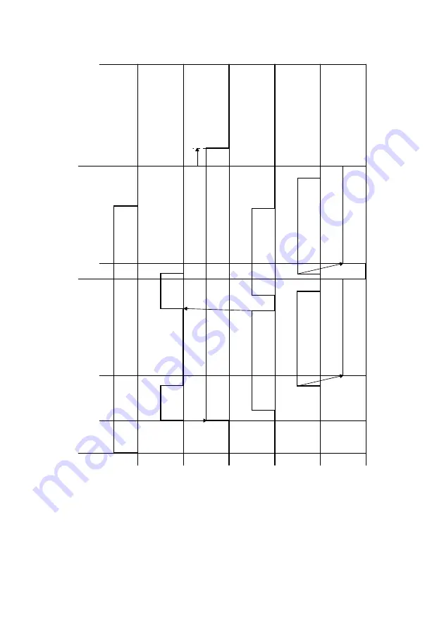
background image

T-8

3.

TIMING CHART

Or

iginal load

ed

St

a

rt

 k

e

y

presse

d

Begin scanning 

of first page

Begin sca

nning 

of

 second pag

e

Finish scanning 

of first page

F

inish

 scanning of 

seco

nd page

F

eeding tw

o A4 L 

pages

H

L

OF

F

ON

Stop

L

H

OF

F

ON

Or

ig

inal Detection 

Sensor

PC1

P

a

per T

a

k

e

-Up 

Clutch

CL1

ADF Ma

in Moto

r

M5

Leading Edge 

Detection Sensor

PC3

Or

ig

inal scann

ing

F

orw

ard 

ro

tatio

n

Summary of Contents for D 16G

Page 1: ...DEVELOP SERVICE MANUAL OPTIONS D 16G 4986 7991 00 ...

Page 2: ......

Page 3: ...INDEX Field Service MAINTENANCE GENERAL CONTROL PANEL SERVICE MODE DESCRIPTIONS DIS REASSEMBLY ADJUSTMENT TROUBLESHOOTING MECHANICAL ELECTRICAL ...

Page 4: ......

Page 5: ...ING SEQUENCE M 6 5 1 Print Start Sequence M 6 1 When the pre start control is not provided M 6 2 When the pre start control is provided M 7 5 2 Print End Sequence M 7 6 IC IMAGING CARTRIDGE SECTION M 8 6 1 Overview M 8 6 2 PC Drum M 10 6 3 Developing System M 11 6 4 Detection of Toner Cartridge M 12 1 Installation detection M 12 2 Interchangeability detection M 12 3 Toner Near Empty and Toner Empt...

Page 6: ...l modes M 27 5 Fusing temperature protect control M 28 13 PAPER EXIT M 29 13 1 Paper Exit Mechanism M 29 14 MISCELLANEOUS M 30 14 1 Cooling of the Printer Interior M 30 14 2 Original Cover Open Close Detection Mechanism M 31 MAINTENANCE 1 MAINTENANCE SCHEDULE E 1 1 1 Guidelines for Life Specifications Values by Unit E 2 1 Life Specifications Values E 2 2 REPLACEMENT CLEANING OF PARTS E 3 1 Cleanin...

Page 7: ...f the Scanner Assy D 19 5 Removal of the Timing Belt D 20 3 5 Disassembly of the Main Drive Section D 21 1 Removal of the Main Motor D 21 2 Removal of the Paper Empty Sensors D 21 3 Removal of the Paper Take Up Solenoid D 23 4 Removal of the Paper Take Up Clutch Gear D 24 5 Removal of the Torque Limiter D 25 6 Disassembly of the Fusing Unit D 26 4 ADJUSTMENTS D 29 4 1 Electrical Image Adjustment D...

Page 8: ...ion Tree S 9 4 2 Service Mode Setting Procedure S 11 4 3 Service Mode Functions S 12 1 Service s Choice S 12 2 Adjust S 14 3 Counter S 17 4 Display S 19 5 Function S 19 6 Fixed Zoom Change S 21 7 Factory Test S 22 8 Clear Data S 22 5 SECURITY MODE S 23 5 1 Security Mode Function Tree S 23 5 2 Security Mode Setting Procedure S 23 1 Security S 23 TROUBLESHOOTING 1 INTRODUCTION T 1 1 1 Electric Compo...

Page 9: ...ALITY PROBLEMS T 24 5 1 Troubleshooting Image Quality Problems T 24 5 2 Initial Checks T 24 5 3 Troubleshooting for Specific Image Quality Problems T 25 1 Image reading system Blank or black prints T 26 2 Image reading system Low image density T 27 3 Image reading system Foggy background or rough image T 28 4 Image reading system Black streaks or bands T 29 5 Image reading system Black spots T 30 ...

Page 10: ......

Page 11: ...GENERAL ...

Page 12: ......

Page 13: ...hotoconductor Electrostatic dry Powdered image transfer to plain paper with laser 600 dpi 600 dpi 600 dpi 300 dpi 2 Way system Tray1 and BypassTray 3 Way system is possible if optional PF 125 Tray2 is installed Unit scanning slit exposure FMT single component developing Rotating brush with pre charge film Roller transfer Curvature separation Charge Neutralizing needle Heat roller Up to Legal size ...

Page 14: ... L or Letter L paper Less than 25 seconds at a room temperature of 23 C and at the rated voltage 16 seconds or less at full size and 600 dpi 300 dpi with plain A4 L or Letter L paper 13 seconds or less at full size and 600 dpi 300 dpi with plain A4 L or Letter L paper If the Start key is pressed more than 3 seconds after open ing and closing the Original Cover or Auto Document Feeder after the eng...

Page 15: ... 770 880 W 220 240 V 740 830 W Power source 110 V 120V 127 V 220 240 V 50 60 Hz Main unit dimensions including Original Cover Main unit weight Width 508 mm 20 inches Depth 608 mm 24 inches Height 408 mm 16 inches 14 9 kg 32 3 4 lb RAM Interfaces Printer Language Fonts Supported Operating Systems Web Browser Share with copier IEEE 1284 Parallel USB Revision 1 1 except for Windows 95 and Windows NT ...

Page 16: ...r Which puts the operator in the direct stream of exhaust from the printer Where ammonia gas might be generated 2 2 Power Source If any other electrical equipment is sourced from the same power outlet make sure that the capacity of the outlet is not exceeded Use a power source with little voltage fluctuation Never connect by means of a multiple socket any other appliances or machines to the outlet...

Page 17: ...g the power cord into the outlet When unplugging the power cord do not pull on the cord hold the plug and pull it out Do not bring any magnetized object near the printer Do not place a vase or vessel containing water on the printer Be sure to turn OFF the power switch at the end of the workday or upon power failure Use care not to drop paper clips staples or other small pieces of metal into the pr...

Page 18: ...hey are to be collected Do not burn bury in the ground or throw into the water any consumables Do not store consumables in a place which Is hot and humid Is subject to direct sunlight Has an open flame nearby 5 MISCELLANEOUS PRECAUTIONS Use the following precautions when performing service jobs for a printer that uses a laser When a service job needs to be performed in the laser beam path such as ...

Page 19: ... 7 6 PARTS IDENTIFICATION 4980G001AA 2 1 3 4 5 6 1 Automatic Document Feeder AF 11 2 Mechanical Counter 3 Expansion memory 32 5 32 MB 4 Paper Feed Cassette PF 125 5 Main Unit D 16G 6 Original Cover OC 7 ...

Page 20: ......

Page 21: ...MECHANICAL ELECTRICAL ...

Page 22: ......

Page 23: ...M 1 1 COMPONENTS LAYOUT 1 IR Unit 5 Paper Take Up Roller 2 Exit Roller 6 Toner Cartridge 3 Fusing Unit 7 Drum Cartridge 4 Image Transfer Section 8 Print Head PH Unit 4980M004AA 8 1 2 3 4 5 6 7 ...

Page 24: ...oes through appropriate correction processes before being output to the PH image processing section 5 PH Image Processing After going through correction processes the digital image signal is converted to a corre sponding electric signal D A conversion based on which control is provided for turning ON or OFF the laser 6 Laser Exposure The laser beam strikes the surface of the PC Drum forming an ele...

Page 25: ...e neutralizes any charge left on the paper 12 Recovery The residual toner on the surface of the PC Drum is temporarily recovered and is made into even finer particles during the print end sequence before being recovered at the Developing Unit 13 Paper Transport The paper is transported onto the Fusing Unit 14 Fusing The developed image is permanently fused to the paper by a combination of heat and...

Page 26: ...ounted the system offers a three way paper supply system The paper taken up and fed in by the Paper Take Up Roll is transported through the printer by the Image Transfer Roller Fusing Roller and Exit Roller and fed out of the printer face down onto the Exit Tray Tray 1 Exit Tray 4980M005AA Multiple Bypass Tray Paper Take Up Roll Image Transfer Roller Fusing Roller Exit Roller ...

Page 27: ...M 5 4 DRIVE SYSTEM 1 Scanner Unit 4 Main Motor 2 Image Transfer Roller 5 Scanner Motor 3 Paper Take up Roller 6 Fusing Roller 4980M010AA 1 2 6 3 4 5 ...

Page 28: ... provided Start key ON Polygon Motor Main Motor Paper Take Up Solenoid S1 DrumCharge Output Exposure Output Develop ing Output Image Transfer Output Drum charge DC Drum charge DC Charge Reverse bias Charge Reverse bias Unexposed area output Negative output ON Negative output 4980M013AA ...

Page 29: ... Transfer Output Drum charge DC Drum charge DC Charge Reverse bias Unexposed area output ON Negative output 4980M017AB 4980M014AA Image Transfer Output Developing Output Polygon Motor Main Motor Drum Charge Output Laser Output Unexposed area illumination PS3 ON ON ON DC Substantially entire surface exposure AC ON Unexposed area illu mination Reverse bias Charge Positive Negative Negative ...

Page 30: ... toner in the Toner Cartridge onto the Toner Supply Roller The Toner Supply Roller transports the toner to the Sleeve Roller The Resin Sleeve of the Sleeve Roller carries the toner onto the PC Drum to form a toner image on the latent image formed on the surface of the PC Drum Imaging Cartridge T C D C PC Drum Toner Supply Roller 4136M504AA Sleeve Roller Toner Agitating Screw Toner Hopper T C 2nd T...

Page 31: ...M 9 The Imaging Cartridge consists of a T C Toner Cartridge and a D C Drum Cartridge see the illustration below 4136M511AA T C Toner Cartridge D C Drum Cartridge Imaging Cartridge 4136M513AA ...

Page 32: ...utmost care to prevent the surface of the PC Drum from being dirtied Grounding of the PC Drum The ground contact point Ground Plate for the PC Drum is located inside the PC Drum at its front side It is at all times in contact with the shaft of the front plate of the Imaging Cartridge When the Imaging Cartridge is loaded in the printer the set pin of the front plate of the Imaging Cartridge contact...

Page 33: ...ns it back to the Toner Hopper The same bias as that applied to the Sleeve Roller is applied to this Bias Seal thereby preventing toner from falling The developing bias automatically adjusts the print image density over a range of seven steps through feedback control A bias voltage reversed from the developing bias is applied before a print command is issued before predrive and during predrive to ...

Page 34: ...r or not the cartridge is loaded in position 2 Interchangeability detection The built in IC chip TC detection board detects the applicable marketing area of the Toner Cartridge when power is turned ON or when the Front Door is opened and closed 3 Toner Near Empty and Toner Empty Detection The Toner Empty Detection Sensor detects the amount of toner still available for use TC Detection Board 4136M5...

Page 35: ...ion sensor exceeds a predetermined period of time is counted When this count reaches a prede termined value a toner near empty or a toner empty condition is detected The toner near empty or toner empty condition is reset when the Front Door is opened and closed Electrical Component Control Signal Blocked Unblocked WIRING DIAGRAM TE1 PWB P MPJ14 2 H L A 5 Toner Detection Window 4136M540AA Reflectin...

Page 36: ...m they produce little ozone Further the charging voltage is low and the deposited charge is even and stable across the surface of the PC Drum The Pre charge Film supplies a preliminary charge to the PC Drum prior to charging by the Drum Charge Brush thereby increasing charging efficiency 1 3 2 4 Drum Cartridge PC Drum Drum Charge Brush Pre charge Film Paper Dust Remover 4136M519AA Drum Cover 4136M...

Page 37: ... 4 Gamma Correction The light reflection data read by the CCD Sensor is translated to corresponding image density data 5 Zoom Processing The synchronous timing of the input data write and output data read is varied to decrease reduction or increase enlargement the number of data readings thereby reducing or enlarging the image in the main and sub scanning direction 6 Background Level Detection The...

Page 38: ... Mirror 3 2nd Mirror Reflects the light reflected off the 1st Mirror directing it to the 3rd 5th Mirror 4 3rd 5th Mirror Reflects the light reflected off the 2nd Mirror directing it to the 4th Mirror Reflects the light reflected off the 4th Mirror directing it to the CCD through the Lens 5 4th Mirror Reflects the light reflected off the 3rd Mirror directing it to the 3rd 5th Mirror 4980M019AA 1 2 ...

Page 39: ...tion is controlled by varying the period of the motor drive pulse that is timed with the reference clock The number of motor drive pulses as determined according to the paper size and zoom ratio controls the amount of movement of the Scanner Electrical Component Control Signal ON OFF WIRING DIAGRAM M4 PWB P P105P 1 4 Pulse output B C 7 4980M002AA Scanner Motor M4 Timing Belt Scanner Assy High spee...

Page 40: ... Construction The laser beam light emitted from the Print Head is used to scan the image as driven by the Polygon Motor Polygon Mirror G2 Lens SOS Mirror SOS Sensor G1 Lens Semiconductor Laser 4136M005AA 1st Mirror 2nd Mirror ...

Page 41: ...the Controller Mechanical Control Board sends a VIDEO signal to the Print Head a given period of time after the leading edge of the paper actu ates the Paper Take Up Switch TOD signal The print start position of a new line as shifted from the previous one is established by transmitting a VIDEO signal after the lapse of an appropriate period of time with refer ence to the SOS Sensor signal The SOS ...

Page 42: ... a laser ON signal The laser ON signal makes a laser beam to be emitted and the laser beam travels to the Polygon Mirror G1 Lens and the SOS Mirror to eventually hit the SOS Sensor which generates an SOS signal The SOS signal determines the laser emission timing for each line in the main scanning direction 4136M517AA SOS Mirror SOS Sensor Polygon Mirror G1 Lens Laser Unit ...

Page 43: ...cal Control Board and the width of the paper The laser emission area is determined by the paper size 2 Sub scanning direction The print start position is determined by the sub scanning print start signal TOD output from the Controller Mechanical Control Board and the length of the paper The laser emission area is determined by the paper size 4980M016AB HSYNC VIDEO VIDEO TOD ...

Page 44: ... paper loaded in the tray is taken up and fed into the printer The actual length of paper is detected based on the period of time through which the Paper Take Up Switch remains actuated or through which the paper moves past the switch and the system speed It is then determined whether or not the actual length matches the paper length specified on the controller Gear with Depressing Cam Tray Paper ...

Page 45: ...paper runs out the actuator drops into the hole in the tray unblocking the Paper Empty Sensor 4 Paper take up retry function To reduce the number of paper misfeeds as a result of a paper take up failure a paper take up retry sequence is carried if the PaperTake Up Switch is not actuated and deac tuated within a predetermined period of time This function is provided for paper take up from any print...

Page 46: ...s in a very little amount of ozone being produced and there is a little chance of a double transferred image occurring To clean the Image Transfer Roller reverse bias is applied to the Image Transfer Roller The cleaning sequence is carried out when the printer is started a print command is issued a print cycle is completed and when the printer is started after a misfeed has been cleared There is t...

Page 47: ... This permanently fixes the toner image in the paper Electrical Parts Control Signal Blocked Unblocked WIRING DIAGRAM PS1 PWB P MPJ8P 3 L H F G 2 Electrical Parts Control Signal Low temp High temp WIRING DIAGRAM TH1 PWB P MPJ2P 1 Analog Input F 2 to 3 Electrical Parts Control Signal ON OFF WIRING DIAGRAM H1 PU 1 CN1PU 1 3 L H I 7 Pressure Roller Fusing Roller Fusing Roller Heater Lamp H1 Fusing En...

Page 48: ...control is resumed when power is turned ON the Front Door is opened and closed or the Energy Save mode is canceled is set according to the mode and the fusing temperature valid before the interruption In the Energy Save mode the Fusing Roller Heater Lamp is turned OFF to reduce power consumption Thermistor detected temperature at temperature control start Less than 50 C 50 C to 125 C 125 C or more...

Page 49: ...de 2 Mode 2 lasts for 208 sec Mode 3 Mode 3 continues until the temperature control is interrupted by opening and closing the Front Door etc 4 Printing temperature by paper type in different temperature control modes 1 Inferior fusing performance can at times result from plain paper having a length of 186 mm or more with the standard fusing temperature setting 200 C The FUSER TEMP Ad setting ofTec...

Page 50: ...otect As a protection should there be a software failure the Thermostat is used to shut down current to the Heater Lamp when the temperature of the Fusing Roller becomes inordi nately high Electrical Component Control Signal Low temp High temp WIRING DIAGRAM TH1 PWB P MPJ2P 1 Analog Input F 2 3 Electrical Component Control Signal ON OFF WIRING DIAGRAM H1 PU 1 CN1PU 1 3 L H I 7 CPU FUSER_LAMP ANIN ...

Page 51: ...en subjected to the fusing process onto the Exit Roller The Exit Sensor detects not only a paper misfeed but also an open Upper Cover Electrical Parts Control Signal Blocked Unblocked WIRING DIAGRAM PS1 PWB P MPJ8P 3 L H F to G 2 Face down Exit Exit Roll Exit Tray Exit Roller 4136M516AA Exit Sensor PS1 ...

Page 52: ...m the outside into the printer interior and discharge heat inside the printer out It thereby prevents the temperature of the PH Unit and the printer interior from increasing Electrical Parts Control Signal ON OFF WIRING DIAGRAM M2 PWB P MPJ13P 1 to 4 Pulse I 3 M3 PWB P MPJ6P 1 to 4 Pulse I 3 4980M001AA PH Unit Cooling Fan Motor 1 M3 Cooling Fan Motor 2 M2 ...

Page 53: ...cover whether the cover is raised or lowered This magnet attracts the Original Cover Set Sensor provided on the printer side thus activating the sensor The printer will then detect the position of the Original Cover Electrical Parts Control Signal Blocked Unblocked WIRING DIAGRAM PS2 PWB O P701O 1 to 2 L H F 9 Original Cover Set Sensor PS2 Magnet 4980M008AA ...

Page 54: ......

Page 55: ...MAINTENANCE ...

Page 56: ......

Page 57: ...nting 2 pages job NOTES K 1 000 printed pages As a rule the Drum Cartridge and Toner Cartridge are to be replaced by the user The contents of the Maintenance List are subject to change without notice For the part numbers see Parts Manual and Parts Modification Notice PM Parts Clean Replace 1 Replace 2 Ref Page in This Manual Paper Take Up Roll When a paper take up failure occurs Replace when a pap...

Page 58: ...ven conditions see the Table given below are met It can be more or less depending on how each individual printer is used 1 Life Specifications Values Print Conditions Job type 2P J Paper size A4 L Letter L B W ratio B W 6 Unit name Life value Detection Toner Cartridge 4 3 K The remaining amount of toner is detected A TONER EMPTY error is detected according to this value ...

Page 59: ...dge E 5 NOTE The Imaging Cartridge is the Drum Cartridge to which the Toner Cartridge is mounted 2 Replacement of the PaperTake Up Roll 1 Remove the Imaging Cartridge E 5 2 Using a soft cloth wipe the surface of the Paper Take Up Roll clean of dirt 4980E006AA 2 Remove the Paper Take Up Roll 4980E007AA ...

Page 60: ...e bushings and the gear to the new Image Transfer Roller NOTES Do not touch or dirty with chemicals or toner the surface of the Image Transfer Roller as indenta tions in and dirt on the surface of the Image Trans fer Roller adversely affect the quality of the printed image When handling the Image Transfer Roller hold onto the shaft and bushings of the roller Do not place a new Image Transfer Rolle...

Page 61: ...ge in the direc tion shown in the illustration and disconnect the Toner Cartridge from the Drum Cartridge NOTE If the Drum Cartridge is to be placed on a floor or similar place use care to prevent toner from scat tering around 4136E007AC 1 Take out a newToner Cartridge and shake it in the horizontal direction sufficiently so that toner is agitated NOTE Placing the Toner Cartridge in an upright pos...

Page 62: ...e 101 B 2 Remove the protective cover from the Toner Car tridge C4136o049AC 3 Install the new Toner Cartridge to the Drum Car tridge NOTE Insert the Toner Cartridge along the guide provided on the Drum Cartridge side and make sure that the Toner Cartridge is not tilted when inserted 4136E009AC 4 Install the Imaging Cartridge in the printer NOTE Insert the Imaging Cartridge along the guide pro vide...

Page 63: ...m Car tridge NOTE Insert the Toner Cartridge along the guide provided on the new Drum Cartridge side and make sure that the Toner Cartridge is not tilted when inserted 4136E012AC 2 Install the Imaging Cartridge in the printer NOTE Insert the Imaging Cartridge along the guide pro vided on the printer side Ensure that the Imaging Cartridge is not slid obliquely 3 Close the Front Door NOTE After repl...

Page 64: ...ve the Rear Cover D 7 2 Unplug one connector on the Controller Mechani cal Control Board 4980E004AA 3 Remove the two screws and then remove the Left Rear Cover 4980U044AA 4 Remove the three screws and then remove the Circuit Board and Metal Bracket 4980E008AA 5 Remove the Upper Left Cover 6 Remove the two screws and then remove the Upper Right Cover and Protective Metal Bracket NOTE The Protective...

Page 65: ... surfaces around the Fusing Unit are very hot Use utmost care not to touch any surfaces other than the Fusing Unit 4980E002AB 8 Remove the Fusing Unit 4980E003AA 1 Connect connector A 2 Mount the Fusing Unit in the printer and secure it in position by tightening the two screws 3 Connect connectors B and C NOTE When installing the Fusing Unit route the harness as shown in the illustration and make ...

Page 66: ......

Page 67: ...DIS REASSEMBLY ADJUSTMENT ...

Page 68: ......

Page 69: ...e Print Head Unit This product employs a Class 3b laser diode that emits an invisible laser beam The laser diode and the scanning polygon mirror are incorporated in the print head unit The print head unit is NOT A FIELD SERVICE ITEM Therefore the print head unit should not be opened under any circumstances Semiconductor laser Maximum power of the laser diode 15 mW Maximum average radiation power 3...

Page 70: ...hed to laser products marketed in the United States All Areas Denmark CAUTION Use of controls adjustments or performance of procedures other than those specified in this manual may result in hazardous radiation exposure Semiconductor laser Maximum power of the laser diode 15 mW Wavelength 770 800 nm CAUTION Use of controls adjustments or performance of procedures other than those specified in this...

Page 71: ...800 nm VARNING Om apparaten används på annat sätt än i denna bruksanvisning specificerats kan användaren utsättas för osynlig laserstrålning som överskrider gränsen för laserklass 1 Halvledarlaser Den maximala effekten för laserdioden 15 mW Våglängden 770 800 nm VARNING Osynlig laserstrålning när denna del är öppnad och spärren är urkopplad Betrakta ej strålen ADVERSEL Dersom apparatet brukes på a...

Page 72: ...Safety Label A laser safety labels is attached to the outside of the machine as shown below 1 4 Laser Caution Label A laser caution label is attached to the inside of the machine as shown below 4980D070AB 4980D061AA ...

Page 73: ...eds to be performed in the laser beam path such as when working around the printerhead and PC Drum be sure first to turn the copier OFF If the job requires that the copier be left ON take off your watch and ring and wear laser protective goggles A highly reflective tool can be dangerous if it is brought into the laser beam path Use utmost care when handling tools on the user s premises ...

Page 74: ...mes unavoidably necessary to disassemble any of these assemblies and units disassembly may be done provided that the conditions permitting reassembly are met Note also that when two or more screws are used on the part in question only one repre sentative screw may be marked with red paint 2 Variable resistors on board Do not turn the variable resistors on boards for which no adjusting instructions...

Page 75: ...D 7 3 DISASSEMBLY REASSEMBLY 3 1 Identification of Exterior Parts and Removal Procedures for Them 4 2 7 1 9 3 C4980o057AB 5 6 C4980o003AC 8 10 ...

Page 76: ...e flat cable and remove the Control Panel D 10 4 Exit tray While pressing out one side remove the Exit tray 5 Front Door Open the Front Door While pressing in one side remove the Front Door 6 Bypass Tray 7 Tray1 Hold down the main unit with one hand and pull Tray1 off toward you 8 Left Cover Open the Front Door Remove the screw unhook the six tabs and remove the Left Cover 9 Right Cover Open the F...

Page 77: ... the following paragraphs omit the removal of the com ponent in question from a connector or a PWB support Where it is absolutely necessary to touch the ICs and other electric components on the board be sure to ground your body Symbol Name Removal Procedures PWB P Controller Mechanical Control Board D 10 PWB O Control Panel D 10 PWB IF Interface Board D 11 PU1 Power Unit D 12 HV1 High Voltage Unit...

Page 78: ...and flat cables from the Controller Mechanical Control Board NOTE Use utmost care not to snap off the flat cable 4980D003AB 3 Remove six screws and the Controller Mechani cal Control Board 4980D004AB 2 Remove the Rubber cap then remove the three screws unplug one connector and one flat cable and then remove the Control Panel NOTE Use utmost care not to snap off the flat cable 4136D047AA ...

Page 79: ...0D063AA 3 Remove the two screws and then remove the Left Rear Cover 4980U044AA 4 Remove the three screws and then remove the Circuit Board and Metal Bracket 4980E008AA 5 Remove the two screws and then remove the Protective Metal Bracket for the Interface Board 4980D065AA 6 Remove the seven screws and then remove the Interface Board 4980D066AA ...

Page 80: ...wo flat cables from the Controller Mechanical Control Board NOTE Use utmost care not to snap off the flat cable 4980D006AA 6 Remove the two screws and then remove the Left Rear Cover 4980D060AA 7 Unplug one connector on the Controller Mechani cal Control Board 4980E004AA 8 Remove the three screws and then remove the Circuit Board and Metal Bracket 4980E008AA ...

Page 81: ...e the four screws and then remove the Metal Bracket 4980D072AA 12 Remove the two screws unhook the tab and then remove the Left Rear Frame 4980D010AC 13 Remove the Upper Left Cover 14 Remove the two screws and then remove the Upper Right Cover and Protective Metal Bracket NOTE The Protective Metal Bracket is tightened together with the Upper Right Cover 4980E001AC ...

Page 82: ... then remove the Fusing Unit Assy 4980E002AA 16 Remove three screws and the Power Switch stay 17 Remove the Power Switch 4980D011AC 18 Remove four screws disconnect three connec tors and remove the Power Unit Assy 4980D026AD 19 Remove four screws and the Power Unit 4136D002AB 2 Remove one screw and the High Voltage Unit 4136D003AB ...

Page 83: ...ht Cover D 7 3 Remove the Rear Cover D 7 4 Unplug the connector 4980D007AA 5 Unplug the two flat cables from the Controller Mechanical Control Board NOTE Be extremely careful not to break the flat cables 4980D006AA 6 Remove the two screws unhook the two tabs and then remove the IR Unit 4980D008AB ...

Page 84: ...am resulting in blindness 1 Remove the IR Unit D 15 2 Remove the Fusing Unit E 8 3 Remove the Exit tray D 7 4 Remove the four screws unhook the four tabs and then remove the Upper Cover 4980D012AB 5 Disconnect one flat cable from the Controller Mechanical Control Board NOTE Use utmost care not to snap off the flat cable 4980D005AA 6 Remove three screws and the PH Unit NOTE When reinstalling the PH...

Page 85: ...D 17 Precautions for Removal Reinstallation of the PH Unit NEVER touch the window on the backside of the PH Unit A dirty window can cause an image problem Window 4136D009AB ...

Page 86: ...al Glass 1 Remove the Original Cover 2 Remove the Control Panel D 7 3 Removal of the Scanner Motor 1 Remove the Original Cover 2 Remove the Upper Cover Assy Original Glass D 18 3 Remove the Left Cover D 7 3 Remove the Original cover set sensor 4980D073AA 3 Remove the six screws and remove the Upper Cover Assy Original Glass 4980D017AB 4 Unplug one connector from the Scanner Motor 4980D007AA ...

Page 87: ...sy Original Glass D 18 5 Remove the two screws and then remove the Scanner Motor Mounting Bracket 4980D018AB 6 Remove the two screws and then remove the Scanner Motor 4980D019AA 3 Remove the two screws and then remove the Flat Cable Holding Plate 4980D020AA 4 Unplug the flat cable 4980D021AA ...

Page 88: ...riginal Cover 2 Remove the Upper Cover Assy Original Glass D 18 3 Remove the Scanner Assy D 19 5 Remove the Timing Belt and shaft and then remove the Scanner Assy 4980D022AA 4 Remove the C clip 5 Remove the washer 6 Remove the Timing Belt 4980D023AB ...

Page 89: ... Door NOTE The Imaging Cartridge is the Drum Cartridge to which the Toner Cartridge is mounted 3 Remove the Left and Right Covers D 7 2 Disconnect one connector 3 Remove two screws two washers and the Main Motor 4136D010AB 4 Remove the four connectors from the Paper Take Up Upper Guide Assy 4980D015AB 5 Unhook the two tabs and then remove the Paper Take Up Upper Guide Assy 4980D016AB ...

Page 90: ...wo tabs and remove the tray 4980D027AC 7 Remove the Multi purpose Tray Paper Empty Sensor 4980D028AB 8 Remove the Multiple Bypass Tray Paper Empty Sensor 4980D029AB 9 Remove the Toner Empty detection sensor 4980D030AA ...

Page 91: ...aper Take Up Solenoid and tighten one screw 2 Turn the gear in the direction of the arrow shown below so that the flapper of the Paper Take Up Solenoid catches the stopper of the gear 2 Disconnect one connector of the Paper Take Up Solenoid 4136D058AA 3 Remove one screw and the Paper Take Up Sole noid 4136D059AA Flapper Gear 4980D067AA Stopper ...

Page 92: ...r of the Main Motor D 21 4980D074AA 6 Remove the Paper Lifting Plate Assy 7 Remove two springs 4980D057AA 8 Disconnect one connector and one flat cable from the Controller Mechanical Control Board NOTE Use utmost care not to snap off the flat cable 9 Remove the Top Cover then remove four screws and the PH Base Plate Assy 4136D016AB 10 Disconnect one connector of the Paper Take Up Solenoid 11 Remov...

Page 93: ...Lim iter is replaced adjust the set position of the Coupling Gear so that the Take up Roller becomes level The procedure is as follow 12 Remove one screw and the Paper Take Up Sole noid 4136D018AA 13 Unhook two tabs and remove the Paper Take Up Clutch Gear 4136D057AA 2 Unhook three tabs and take apart the Paper Take Up Clutch Gear then remove the Torque Limiter 4136D043AA Torque Limiter Coupling G...

Page 94: ...placed Paper Take Up Clutch Gear Torque Limiter to the shaft Rotate the Paper Take Up Clutch Gear by hand Need to be released Sole noid Flapper 4136D060AA 1 When the Roller is leant to clockwise move the coupling Gear to A direction 4136D046AA 2 When the Roller is leant to counter clockwise move the coupling Gear to B direction 4136D045AA 2 Remove the two screws and then the Fusing Unit is divided...

Page 95: ...of the glass of the Fusing Roller Heater Lamp with bare hands When reinstalling the Fusing Roller Heater Lamp make sure that the side of the lamp having a volt age marking faces the gear side 4136D023AB 6 Pull out the drive gear from the Fusing Roller 7 Pull out the Fusing Roller NOTE When removing and reinstalling the Fusing Roller keep the Fusing Roller Paper Separator Fingers in their raised po...

Page 96: ...D 28 9 Remove one screw and the Thermistor NOTE When reinstalling the Thermistor route the har ness as shown in the illustration 10 Remove two screws and the Thermostat 4980D068AA ...

Page 97: ...ing the ADJUST Menu 1 Enter the Service mode 2 Press the Zoom Select key to select the ADJUST menu 3 Printing a Test Pattern NOTES Print a test pattern when making the following adjustments Printer s main scanning sub scanning registration adjustments Scanner s main scanning sub scanning registration adjustments Scanner s zoom ratio adjustment 1 Enter the Service mode 2 Press the Density Select ke...

Page 98: ...verview To reduce the margin Decrease the setting To increase the margin Increase the setting 4 Specify settings for the TRAILING EDGE ERASE and the VERTICAL EDGE ERASE functions in the same way Mode Function Item Setting Range Service s Choice Leading Edge Erase Trailing Edge Erase Vertical Edge Erase 0 to 5 1 increment 1 mm Specify the amount erased at the leading edge width of A trailing edge w...

Page 99: ...tting If the width of B is less than the width of A Decrease the setting If the shift cannot be adjusted to within the specification with a single adjustment perform the adjustment again to change the setting 5 Press the Yes key to apply the setting NOTE If the Stop key is pressed instead of the Yes key the main screen is displayed and the set ting returns to that before it was changed 6 Print a t...

Page 100: ...tern is longer than the specified width Increase the set ting If the width of C in the test pattern is shorter than the specified width Decrease the setting If the shift cannot be adjusted to within the specification with a single adjustment perform the adjustment again to change the setting 5 Press the Yes key to apply the setting NOTE If the Stop key is pressed instead of the Yes key the main sc...

Page 101: ... If the width of D is out of specification adjust it according to the following procedure 5 Change the setting If the width of D in the test pattern is longer than the specified width Decrease the setting If the width of C in the test pattern is shorter than the specified width Increase the set ting If the shift cannot be adjusted to within the specification with a single adjustment perform the ad...

Page 102: ...he Stop key is pressed instead of the Yes key the main screen is displayed and the set ting returns to that before it was changed Place the test pattern on the Original Glass again make another test copy and check it ...

Page 103: ... If the width of E is out of specification adjust it according to the following procedure 5 Change the setting If the width of E in the test pattern is longer than the specified width Decrease the set ting If the width of C in the test pattern is shorter than the specified width Increase the set ting If the shift cannot be adjusted to within the specification with a single adjustment perform the a...

Page 104: ...he Stop key is pressed instead of the Yes key the main screen is displayed and the set ting returns to that before it was changed Place the test pattern on the Original Glass again make another test copy and check it ...

Page 105: ...py of the test pattern are shifted If the shift is out of specification adjust it according to the following procedure 5 Change the setting If the width of A is less than the width of B Increase the setting If the width of B is less than the width of A Decrease the setting If the shift cannot be adjusted to within the specification with a single adjustment perform the adjustment again to change th...

Page 106: ...he Stop key is pressed instead of the Yes key the main screen is displayed and the set ting returns to that before it was changed Place the test pattern on the Original Glass again make another test copy and check it ...

Page 107: ... If the width of C in the test pattern is longer than the specified width Increase the set ting If the width of C in the test pattern is shorter than the specified width Decrease the setting If the shift cannot be adjusted to within the specification with a single adjustment perform the adjustment again to change the setting 6 Press the Yes key to apply the setting NOTE If the Stop key is pressed ...

Page 108: ...unter Option 1 Remove the Right Cover D 7 2 Remove the Rear Cover D 7 3 Unplug one connector on the Controller Mechani cal Control Board 4980D055AA 4 Remove the Relay Harness 4980D056AA 5 Remove the screw and then remove the Mechanical Counter 4137U003AA ...

Page 109: ...orresponding_language WinXP on the CD ROM and then click the OK button 7 Click the Next button and then click the Finish button 8 When the Found New Hardware Wizard dialog box appears again repeat steps 4 through 7 to install all drivers For Windows 2000 1 Start up the host computer and then insert the CD ROM into the CD ROM drive 2 Turn on the printer 3 Use a USB cable to connect the printer to t...

Page 110: ...y device recommended and then click the Next button again 5 Select Specify a location and then click the Browse button 6 Specify Corresponding_language Win9X on the CD ROM and then click the OK button 7 Click the OK button and then continue following the instructions in the dialog boxes that appear until the Completing the Found New Hardware Wizard dialog box appears 8 Click the Finish button 9 Wh...

Page 111: ...computer Wait until the hardware is detected 5 Display the System Properties dialog box Properties for My Computer click the Hardware tab click the Device Manager button select Imaging devices and then check that Develop D 16G has been added 6 Double click Update file in the Update Software folder The Develop Update F W V1 XX dialog box appears 7 Click the Browse button and then select Update file...

Page 112: ... display NOTE Do not turn the printer off or on while the screen shown above is displayed 10 Check that the following message appears in the display to indicate that the updating of the firmware is complete 11 Click the OK button and then quit the Develop Update F W V1 XX application 12 Turn the printer off then on again 4980D050AB 4980D051AB 4980D049AA ...

Page 113: ...r jumper switches CJ1 and CJ2 on the Controller Mechanical Control Board from 1 2 to 2 3 5 Attach Service Download BIOS U19 and U26 to memory sockets U19 and U26 on the Controller Mechanical Control Board 6 Use a USB cable to connect the printer to the host computer 7 Start up the host computer 4980D052AA U19 U26 CJ1 CJ2 CJ1 CJ2 4980D069AA Service Download BIOS U19 and U26 Parts No 4980 1157 xx ...

Page 114: ...isplay to indicate that the updating of the firmware has been completed correctly 11 Turn off the printer 12 Change the settings for jumper switches CJ1 and CJ2 on the Controller Mechanical Control Board from 2 3 to 1 2 Return them to their default settings 13 Remove Service Download BIOS U19 and U26 from memory sockets U19 and U26 on the Controller Mechanical Control Board 14 Turn on the printer ...

Page 115: ...ontrol Board to the new one Remove the EEPROM U39 from the old Controller Mechanical Control Board and then attach it to the new Controller Mechanical Control Board 4980D059AB EEPROM Old Controller Mechanical Control Board New Controller Mechanical Control Board NOTE Be sure to install the EEPROM U39 so that notch A faces the correct direction 1171D049AA A A ...

Page 116: ......

Page 117: ...CONTROL PANEL SERVICE MODE DESCRIPTIONS ...

Page 118: ......

Page 119: ...urn to the previous screen Press to specify various settings 6 Yes key Press to apply the specified setting Press to specify various settings 7 10 Key Pad Use to type in the number of copies to be made and any other numeric data 8 Stop key Press to stop the print operation Press to stop the scan operation The indicator lights up in orange when the machine is paused or while copying 9 Panel Reset k...

Page 120: ...om ratio from the preset fixed ratios 13 Paper key Press to select the paper in the desired paper tray 14 key Press to adjust the image density Press to specify various settings 15 Auto Photo key Press to change the image density mode 16 Status key Press to display each counter value 17 Sort key Press to select the Sort function 18 2in1 key Press to select the 2in1 copy function No Key Name Functi...

Page 121: ...S 3 2 FUNCTIONS OF SWITCHES AND PARTS ON PWBs 2 1 Circuit Board Locations 2 2 PWB P Controller Mechanical Control Board PWB IF PWB P 4980S002AA 4980S003AB M32 5 Option Socket ...

Page 122: ...S 4 2 3 PWB IF Interface Board 4980S004AA USB port IEEE1284 parallel port ...

Page 123: ... MODE MACHINE SETTING 1 AUTO PANEL RESET 2 ENERGY SAVE MODE 3 DENSITY ADF 4 DENSITY BOOK 5 PRINT DENSITY 6 LCD CONTRAST 7 LANGUAGE 8 LAMP OFF TIME 1 TRAY1 PAPER 2 TRAY SETTING PAPER SOURCE SETUP COPY SETTING 1 PAPER PRIORITY 2 DENSITY PRIORITY 3 DENSITY LEVEL A 4 DENSITY LEVEL M 5 OUTPUT PRIORITY 6 RESOLUTION ...

Page 124: ...T To specify the time until the auto panel reset operation is performed after a copy cycle has been com pleted or after the last key opera tion The default setting is 1 minute OFF ON 0 5 1 2 3 4 5 2 ENERGY SAVE MODE To specify the time until the machine enters Energy Save mode after a copy cycle has been completed or after the last key operation The default setting is 15 min utes The length of tim...

Page 125: ...ng range is 1 to 2 7 LANGUAGE To specify the language of screens The default setting is ENGLISH The language settings are divided into Type 1 and Type 2 The Type 1 languages are the standard Available Languages Type1 ENGLISH GERMAN FRENCH ITALIAN DANISH DUTCH SPANISH NORWEGIAN SWEDISH FINNISH TURKISH PORTUGUESE Type2 ENGLISH GERMAN FRENCH CZECH HUNGARIAN POLISH ROMANIAN LITHUANIAN SLOVAKIAN 8 LAMP...

Page 126: ...t setting is CON TINUOUS FIXED CONTINUOUS No Function Purpose Setting Details Precautions 1 PAPER PRIORITY To specify the paper tray that is given priority The default setting is TRAY1 TRAY1 TRAY2 2 DENSITY PRI ORITY To specify the image density set ting that is selected when the machine is turned on or the Panel Reset key is pressed The default setting is AUTO AUTO MANUAL PHOTO 3 DENSITY LEVEL A ...

Page 127: ... ERASE FLS PAPER SIZE GDI TIMEOUT TONER EMPTY STOP PRE ROTATION FUSER TEMP Ad PRN MAIN REGIST PRN SUB REGIST CCD MAIN ZOOM CCD SUB ZOOM CCD MAIN REGIST CCD SUB REGIST ADF SUB ZOOM ADF MAIN REGIST ADF SUB REGIST ADJUST COUNTER DISPLAY TOTAL COUNTER PM COUNTER I C COUNTER APPLICATION COUNTER SCAN COUNTER PRINTER JAM COUNTER ADF JAM COUNTER TROUBLE COUNTER MAIN F W VER ENGINE F W VER MAIN RAM SIZE SE...

Page 128: ...ORY CLEAR PM COUNTER I C COUNTER APPLICATION COUNTER SCAN COUNTER PRINTER JAM COUNTER ADF JAM COUNTER TROUBLE COUNTER PAPER FEED TEST PRINT TEST PATTERN ADF FEED TEST COPY ADF GLASS AREA CCD MOVE TO HOME SCAN TEST FACTORY TEST PANEL BUZZER TEST RAM TEST ...

Page 129: ...rst Service mode screen appears Exiting Procedure Press the Panel Reset key Changing the Settings for Service Mode Functions 1 Press the Zoom Select key to select the desired function 2 Press the Zoom Select key Density Select key or the 10 Key Pad to select the desired setting 3 Press the Yes key to apply the setting 4 To return to the previous screen press the No C key NOTE In order for the sett...

Page 130: ... the PH unit has been replaced The default setting is 4mm 0mm 1mm 2mm 3mm 4mm 5mm VERTICAL EDGE ERASE To change the laser emission tim ing to adjust the width of the image area that is erased on both sides CD direction When the PH unit has been replaced Select the value for the width erased in the CD direction The default setting is 4mm 0mm 1mm 2mm 3mm 4mm 5mm FLS PAPER SIZE To specify the paper s...

Page 131: ...e default setting is OFF ON OFF If OFF is selected the length of time until the first copy can be printed is shorter FUSER TEMP Ad To specify the fusing temperature when using plain paper more than 186 mm When a fusing failure has occurred The default setting is 0 0 Standard 1 Higher Function Purpose Setting Details Precautions ...

Page 132: ...curacy by varying the scanning zoom ratio in the main scanning direction When the Timing Belt has been replaced When the Scanner Assy has been replaced Press the Start key to begin printing the test page ADJUST The setting range is 95 to 105 1 increment 0 4 CCD SUB ZOOM TEST COPY To adjust for variations in the accu racy of IR parts and their mounting accuracy by varying the scanning zoom ratio in...

Page 133: ...and their mounting accuracy by varying the scanning start position in the main scanning direction when using the Automatic Document Feeder When the Upper Cover Assy Original Glass has been replaced Press the Start key to begin printing the test page ADJUST The setting range is 90 to 110 1 increment 0 5 mm ADF SUB REGIST TEST COPY To adjust for variations in the accu racy of all parts and their mou...

Page 134: ... unit Once the type of Toner Cartridge is specified TC TYPE on the ADJUST menu cannot be set again Types of Toner Cartridges ME Toner Cartridge 101 A Others Toner Cartridge 101 B MC Toner Cartridge 101 C The default setting differs depending on the marketing area Function Purpose Setting Details Precautions Toner Cartridge Type Setting No Toner Cartridge 0 Not Used 1 A 2 B 3 Not Used 4 C 5 Not Use...

Page 135: ...the CLEAR DATA menu of Ser vice mode APPLICATION COUNTER To display the number of pages used with each application COPY PRINT Number of cop ies printed FAX RX PRINT Not Used REPORT PRINT Not Used PC PRINT Number of com puter printouts printed FAX TX PAGE Not Used MAIL TX PAGE Not Used To clear the counter data use the functions on the CLEAR DATA menu of Ser vice mode SCAN COUNTER To display the nu...

Page 136: ...OUBLE COUNTER To display the number of times each error was detected C0045 Fuser fan error C0210 Transfer voltage error C0500 Fuser Warm up error C0510 Fuser temperature low C0520 Fuser overheat C0650 Home sensor error Scanner motor error C1200 ASIC memory abnormal C1300 Polygon mirror motor error C133B Communication with option error C133C Modem error C133D ROM checksum error C13F0 Laser error C1...

Page 137: ...paper tray 2 Press the Start key to begin testing paper feeding 3 Press the Stop key to stop testing paper feeding PRINT TEST PAT TERN TEST PAT TERN 1 To print the test pattern for adjust ing the image If there is tilt or when registration or zoom ratio adjustments are performed Procedure 1 Select the paper tray 2 Select the test pattern type 3 Press the Start key to print the test pattern TEST PA...

Page 138: ...he COPY ADF GLASS AREA function CCD MOVE TO HOME To move the scanner to its home position in order to secure the scanner When transporting the machine NOTE When transporting the machine be sure to move the scanner to its home position and secure it with the stopper at the bottom left of the IR SCAN TEST To check the lighting of the Expo sure Lamp and the movement of the scanner If the scanner malf...

Page 139: ... OEM1 Inch Setting Name Initial fixed zoom ratio Setting Range Reduction 2 70 51 to 70 Reduction 1 81 71 to 99 Expansion 1 115 101 to 140 Expansion 2 141 141 to 199 Setting Name Initial fixed zoom ratio Setting Range Reduction 2 64 51 to 64 Reduction 1 78 65 to 99 Expansion 1 129 101 to 153 Expansion 2 154 154 to 199 Setting Name Initial fixed zoom ratio Setting Range Reduction 2 64 51 to 64 Reduc...

Page 140: ...e Utility mode All functions in the Services Choice menu of the Service mode All functions in the ADJUST menu of the Service mode except SERIAL NO CUSTOMER ID and TC TYPE All FIXED ZOOM settings in the Service mode All Security mode settings in the Service mode NOTE After the MEMORY CLEAR function is performed turn the machine off then on again PM COUNTER To clear the PM COUNTER value I C COUNTER ...

Page 141: ... 1 Display the Service mode screen S 11 2 Press the Stop key then the 9 key 3 The Security mode screen appears Exiting Procedure Press the Panel Reset key 1 Security Function Purpose Setting Details Precautions MACHINE COUNTER To enable or disable copying depending on whether or not the Mechanical Counter is installed The default setting is ENABLE ENABLE DISABLE NOTE If ENABLE is selected copying ...

Page 142: ......

Page 143: ...TROUBLESHOOTING ...

Page 144: ......

Page 145: ... used to check to see if an electric component is fully operational when a paper misfeed or a malfunction occurs in the printer 1 Sensors Step Check Result Action 1 Does the input signal to the Controller Mechanical Control Board go from HIGH to LOW or vice versa when the sensor is blocked NO Replace the sensor YES Replace the Con troller Mechanical Control Board 4025T520AA 4025T521AA ...

Page 146: ...is actuated NO Replace the switch YES Replace the Con troller Mechanical Control Board Step Check Result Action 1 Does the output signal from the Controller Mechani cal Control Board go from HIGH to LOW when the solenoid is energized NO Replace the Con troller Mechanical Control Board YES Replace the sole noid Not Use COM NO 4025T523AB 1 2 2 1 2 1 4025T522AA ...

Page 147: ...chanical Control Board go from HIGH to LOW when the motor is energized YES Replace the motor NO Replace the Con troller Mechanical Control Board Step Check Result Action 1 Does the input signal to the Controller Mechanical Control Board go from HIGH to LOW when the motor is energized The input signal varies depending on the direction of rotation YES Replace the motor NO Replace the Con troller Mec...

Page 148: ...e hookup connector of the motor and print jack on the Controller Mechanical Control Board con nected properly YES Replace the motor or the Controller Mechanical Control Board NO Connect the con nector or the print jack properly 4025T527AA ...

Page 149: ...oting pro cedures for paper misfeeds malfunctions and image problems 4980T001AA Control Panel PWB O Paper Feed Cassette Controller Mechanical Control Board PWB P DC Stabilized Power Unit PU PH Unit Automatic Docu ment Feeder Main Unit Drive System Control System Line Image Reading IR Drive System High Voltage Unit HV1 ...

Page 150: ...led wavy or damp Replace paper Instruct user in correct paper storage Is the paper transport path deformed dirty or obstructed with foreign matter Clean the paper path and replace if necessary Are the Paper Separator Fingers dirty deformed or worn Replace Fusing Unit Is the roller dirty deformed or worn Clean the roller and replace if neces sary Are Edge Guides at correct position to accommo date ...

Page 151: ...splay when a paper mis feed occurs Paper Take Up Section Misfeed Transport Section Misfeed Procedure for cancelling the misfeed display 1 Open the appropriate covers remove the misfed paper and any remaining paper and then close the covers 2 Open then close the Front Door 4980P555DA 4980P502DA ...

Page 152: ...T 8 2 3 Locations of Misfeed Detection Sensors 4980M005AA Exit Sensor PS1 Paper Take Up Switch S1 ...

Page 153: ...mined period of time has elapsed after the Paper Take Up Switch is turned on The Paper Take Up Switch is not turned off after the predetermined period of time has elapsed after the Paper Take Up Switch is turned on Relevant Electrical Parts Paper Take Up Switch S1 Exit Sensor PS1 Paper Take Up Solenoid SL1 Controller Mechanical Control Board PWB P Step Action Ref Page WIRING DIAGRAM Control Signal...

Page 154: ...e is turned on The Paper Take Up Switch is turned on or the Exit Sensor is blocked Remains paper Jam 2 Paper exit jam The Exit Sensor is unblocked slower than the predetermined period of time after the Paper Take Up Switch is turned on Relevant Electric Parts Paper Take Up Switch S1 Exit Sensor PS1 Controller Mechanical Control Board PWB P Step Action Ref Page WIRING DIAGRAM Control Signal Locatio...

Page 155: ...Malfunction Name Description C0045 Fuser fan motor error The LOCK signal remains HIGH or LOW continuously for a predetermined period of time while the Cooling Fan Motor remains energized C0210 H V abnormal The Drum Charge Monitor Voltage HVC_MON signal falls outside a predetermined range at any time after the lapse of a predetermined period of time after the Power Switch has been turned ON The Ima...

Page 156: ... set temperatures are as follows 140 C during a print mode at 600 dpi 70 C during the standby mode C0520 Fuser overheat The temperature detected by the Thermistor remains higher than 235 C for a predetermined period of time while the fusing temperature control is being provided C0650 Scanner home sen sor error The Scanner Home Position Sensor is not detected within the predetermined period of time...

Page 157: ... limit value The laser output remains lower than the lower limit value C1468 EEPROM error An EEPROM not written with initial data was detected C14A3 IR lamp malfunc tion The luminosity level of the Exposure Lamp is not stabi lized within the predetermined period of time Malfunc tion Code Malfunction Name Description ...

Page 158: ... remains energized Relevant Electric Parts Cooling Fan Motor M2 Controller Mechanical Control Board PWB P Power Unit PU1 Step Action Ref Page WIRING DIAGRAM Control Signal Location Electric Parts 1 Check the Motor connectors for connection and correct as neces sary 2 Check the fan for possible over load and correct as necessary 3 M2 operation check T 3 PWB P MPJ13P 1 to 3 pulse G to H 5 to 6 4 M3 ...

Page 159: ...termined period of time after the Power Switch has been turned ON The Image Transfer Voltage Monitor signal T_MON_V and Image Transfer Current Monitor signal T_MON_I fall outside a corresponding predetermined range Relevant Electric Parts Fusing Unit Controller Mechanical Control Board PWB P Step Action Ref Page WIRING DIAGRAM Control Signal Location Electric Parts 1 Replace Fusing Unit 2 Replace ...

Page 160: ...ec period or more for the period of time that begins after the lapse of a predetermined period of time after the Fusing Roller Heater Lamp has been turned ON and ends when the lamp is turned OFF The Fusing Roller Heater Lamp remains ON for a 30 sec period or more except during the period through which the Main Motor remains energized Relevant Electric Parts Fusing Unit Thermistor TH1 Fusing Roller...

Page 161: ...s are as follows 140 C during a print mode at 600 dpi 70 C during the standby mode Relevant Electric Parts Fusing Unit Thermistor TH1 Fusing Roller Heater Lamp H1 Controller Mechanical Control Board PWB P Thermostat TS1 Power Unit PU1 Step Action Ref Page WIRING DIAGRAM Control Signal Location Electric Parts 1 Replace Thermistor TH1 2 Replace Fusing Roller Heater Lamp H1 3 Replace Thermostat TS1 4...

Page 162: ... Thermostat TS1 Power Unit PU1 Step Action Ref Page WIRING DIAGRAM Control Signal Location Electric Parts 1 Replace Thermistor TH1 2 Replace Fusing Roller Heater Lamp H1 3 Replace Thermostat TS1 4 Replace Fusing Unit 5 Replace Controller Mechanical Control Board PWB P 6 Replace Power Unit PU1 Description The Scanner Home Position Sensor is not detected within the predetermined period of time after...

Page 163: ...PWB P Description The LOCK signal is not detected within a predetermined period of time that begins 1 sec after the Polygon Motor has been energized No new LOCK signal is detected for a 1 sec period that begins 1 5 sec after the first LOCK signal was detected The LOCK signal is not detected for a continuous 0 5 sec period in a state in which the Polygon Motor runs stably The LOCK signal remains ON...

Page 164: ...roller Control Board within 5 sec onds while printing Relevant Electrical Components Controller Mechanical Control Board PWB P Step Action Ref Page WIRING DIAGRAM Control Signal Location Electric Parts 1 Replace PWB P Description A malfunction occurred in the ROM Relevant Electrical Components Controller Mechanical Control Board PWB P Step Action Ref Page WIRING DIAGRAM Control Signal Location Ele...

Page 165: ... Page WIRING DIAGRAM Control Signal Location Electric Parts 1 Check cables for connection and correct as necessary 2 Replace PH Unit 3 Replace PWB P Description An EEPROM not written with initial data was detected Relevant Electric Parts Controller Mechanical Control Board PWB P Step Action Ref Page WIRING DIAGRAM Control Signal Location Electric Parts 1 Unplug then plug in the power cord and turn...

Page 166: ...amp is not stabilized within the predetermined period of time Relevant Electric Parts IR Unit Controller Mechanical Control Board PWB P Step Action Ref Page WIRING DIAGRAM Control Signal Location Electric Parts 1 Check the connection of the connectors and then correct them if necessary 3 Replace PWB P 4 Replace the Scanner Assy ...

Page 167: ...Action 1 Is the power cord plugged into the power outlet NO Plug the power cord into the power outlet 2 Is the power cord connected properly to the printer NO Plug the power cord into the printer 3 Is the Power Switch turned ON NO Turn ON the Power Switch 4 Are the fuses F101 and F102 on the Power Unit conducting NO Replace Power Unit PU1 YES Replace Controller Mechan ical Control Board PWB P ...

Page 168: ...ca tions NO Instruct the user to use recom mended paper that meets prod uct specifications 3 The paper is damp YES Change the paper Instruct the user on the correct methods for stor ing paper Original document 4 The document is not flat YES Correct the docu ment 5 Copies of a faint document written in light pencil etc are being made YES Instruct the user to use a docu ment with an appropriateimage...

Page 169: ...re is attributable to the input system Image Reading Section or the output system Engine section Check Result Cause Copy made at a reduced zoom ratio Input image reading system Output printer system 1177T03YA 1177T04YA Full size copy Reduced copy 1177T05YA Full size copy Reduced copy ...

Page 170: ...ep Check Result Action 1 Are there no bent connector pins on the cables connecting the control boards are all connectors correctly plugged in and are no cables broken NO Correctly plug in the connectors Replace connection cables 2 Does the Exposure Lamp light up NO Replace the Scanner Assy 4011T035AA 4011T036AA ...

Page 171: ...or back surface of the Original Glass dirty YES Clean them 3 Are the mirror or lens dirty YES Clean them Replace the Scanner Assy 4 Is the Exposure Lamp dirty YES Clean it Replace the Scanner Assy 5 Are there no bent connector pins on the cables connecting the control boards are all connectors correctly plugged in and are no cables broken NO Correctly plug in the connectors Replace connection cabl...

Page 172: ...e flat YES If the Original Cover is deformed or the hinges are damaged replace the Original Cover 5 Is the surface of the Original Glass dirty YES Clean it 6 Are the Shading Sheet or back surface of the Original Glass dirty YES Clean them 7 Are the mirror or lens dirty YES Clean them Replace the Scanner Assy 8 Is the Exposure Lamp dirty YES Clean it Replace the Scanner 9 Are there no bent connecto...

Page 173: ...ged replace the Original Cover 4 Is the surface of the Original Glass dirty YES Clean it 5 Are the Shading Sheet or back surface of the Original Glass dirty YES Clean them 6 Are the mirror or lens dirty YES Clean them Replace the Scanner Assy 7 Is the Exposure Lamp dirty YES Clean it Replace the Scanner Assy 8 Are there no bent connector pins on the cables connecting the control boards are all con...

Page 174: ...ooting Procedures Step Check Result Action 1 Is the document damaged or dirty YES Replace the document 2 Is the Original Pad dirty YES Clean it 3 Is the Original Glass dirty YES Clean it 4 The problem has been eliminated after performing step 3 NO Replace the Scanner Assy 4011T521AA ...

Page 175: ...ged replace the Original Cover 4 Is the surface of the Original Glass dirty YES Clean it 5 Are the Shading Sheet or back surface of the Original Glass dirty YES Clean them 6 Are the mirror or lens dirty YES Clean them Replace the Scanner Assy 7 Is the Exposure Lamp dirty YES Clean it Replace the Scanner Assy 8 Are there no bent connector pins on the cables connecting the control boards are all con...

Page 176: ... Correct it 3 Is there enough slack in the Timing Belt NO Correct it Replace the Timing Belt 4 Are the Scanner Rails scratched or dirty YES Clean them 5 Are there no bent connector pins on the cables connecting the control boards are all connectors correctly plugged in and are no cables broken NO Correctly plug in the connectors Replace connection cables 6 The problem has been eliminated after per...

Page 177: ...for connection and correct as necessary or replace Imaging Cartridge Drum Cartridge Toner Car tridge 3 Is the drum charge voltage contact point or PC Drum ground contact point of the Imag ing Cartridge properly connected NO Check clean or correct con tact point 4 Is the High Voltage Unit HV1 connector connected properly NO Connect it properly 5 Is the problem eliminated when step 4 was checked NO ...

Page 178: ...ge 3 Is there foreign matter on paper path YES Remove foreign matter 4 Is Image Transfer Roller dirty or scratchy 3 YES Replace Image Transfer Roller Replace High Voltage Unit HV1 Replace Controller Mechani cal Control Board PWB P Step Check Result Action 1 Is there foreign matter on paper path YES Remove foreign matter 2 Is Fusing Roller dirty or scratchy YES Replace Fusing Unit Fusing Roller 3 I...

Page 179: ...here toner left in Toner Cartridge NO Replace Toner Cartridge 3 Is PC Drum faulty life YES Replace Drum Cartridge 4 Is developing bias faulty YES Replace High Voltage Unit HV1 Replace Controller Mechani cal Control Board PWB P 5 Is image transfer faulty YES Replace Image Transfer Roller Replace High Voltage Unit HV1 Replace Controller Mechani cal Control Board PWB P 4011T003AA ...

Page 180: ...place Drum Cartridge 2 Is developing bias contact terminal in good contact with the mating part NO Clean contact terminal or check terminal position 3 Is PH window dirty YES Clean 4 Is the problem eliminated after checks have been made up to step 3 NO Replace High Voltage Unit HV1 Replace Controller Mechani cal Control Board PWB P 4011T004AA ...

Page 181: ...ratchy or dirty YES Replace Image Transfer Roller 2 Is PC Drum scratchy or dirty YES Replace Drum Cartridge 3 Is Fusing Roller scratchy or dirty YES Replace Fusing Unit Fusing Roller 4 Is PH window dirty YES Clean 5 Is the problem eliminated after checks have been made up to step 4 NO Replace Controller Mechani cal Control Board PWB P 4011T015AA 4011T020AA ...

Page 182: ...cratchy or dirty YES Replace Drum Cartridge 3 Is Fusing Roller scratchy or dirty YES Replace Fusing Unit Fusing Roller 4 Is the problem eliminated after checks have been made up to step 3 NO Replace Controller Mechani cal Control Board PWB P Step Check Result Action 1 Is Fusing Roller faulty YES Replace Fusing Unit Fusing Roller 2 Is Image Transfer Roller faulty YES Replace Image Transfer Roller 4...

Page 183: ...m Flexible Sleeve is scratchy or dirty YES Replace Toner Car tridge 3 Is uneven image at a pitch of 75 3 mm Pressure Roller is scratchy or dirty YES Replace Fusing Unit 4 Is uneven image at a pitch of 94 2 mm PC Drum is scratchy or dirty YES Replace Drum Cartridge Fusing Roller is scratchy or dirty YES Replace Fusing Unit 51 mm pitch uneven image 4136T004AA 75 3 mm pitch uneven image 4136T005AA 94...

Page 184: ...DEVELOP Copyright 2003 Develop Printed in Germany ...

Page 185: ...AF 11 Service Manual ...

Page 186: ...Up Roller D 4 5 Cleaning of the Registration Rollers D 4 6 Cleaning of the Transport Roller D 4 7 Cleaning of the Exit Roller D 4 8 Cleaning of the Paper Separator Pad D 5 9 Removal of the Paper Separator Pad D 5 3 DISASSEMBLY REASSEMBLY D 6 3 1 Names Removal of External Parts D 6 3 2 Removal of Circuit Boards D 7 1 Removal of the Automatic Document Feeder Control Board D 7 3 3 Disassembly D 8 1 R...

Page 187: ... 1 1 Sensors T 1 2 Clutches T 2 3 Motors T 2 2 PAPER MISFEED T 4 2 1 Initial Check Items T 4 2 2 Paper Misfeed Displays T 5 2 3 Locations of Misfeed Detection Sensors T 6 2 4 Misfeed Detection Timing and Troubleshooting Procedures T 7 1 The Original misfeeds T 7 3 TIMING CHART T 8 ...

Page 188: ...GENERAL ...

Page 189: ...sheets 80 g m2 21 lb Center Face up 12 sheets minute with plain A4 L or Letter L paper Standard mode DC 24 V DC 5 V supplied by main unit Less than 30 W W 497 mm 19 1 2 in D 355 mm 14 in H 80 mm 3 1 4 in 3 2 kg 7 lb Same as the copier Original types Possible problems Originals bound with staples or paper clips Incorrect paper take up damaged originals or drive malfunctions due to jammed paper clip...

Page 190: ...MECHANICAL ELECTRICAL ...

Page 191: ...M 1 1 COMPONENTS LAYOUT 1 Pick up Roller 4 Transport Roll 2 Exit Roller 5 Take up Roller 3 Transport Roller 1 1382M005AA 2 3 4 5 ...

Page 192: ...M 2 2 DRIVE SYSTEM 1 Pick up Roller 4 Transport Roller 2 Take up Roller 5 Exit Roller 3 Document Feed Shaft 1382M007AA 1 2 4 3 5 ...

Page 193: ...AYOUT PWB A AF AF Control Board M5 AF Main Motor PC2 Paper take Up Sensor S3 AF door set switch CL1 Paper take Up clutch PC1 Original detection Sensor PC3 Leading Edge Detection Sensor PC3 PC2 PWB A AF 1382M006AA M5 CL1 S3 PC1 ...

Page 194: ...on of the Pick up Roller The Pick up Roller and Take up Roller turn to take up and feed the original properly The Pick up Roller transports the original up to the Take up Roller The AF Main Motor drives the Pick up Roller and Take up Roller through a gear train and the Paper Take up Clutch Electrical Component Control Signal ON OFF WIRING DIAGRAM M5 PWB A AF PA01OA AF 1 4 Pulse output F G 2 3 CL1 ...

Page 195: ...e Take up Roller and Separator Pad is equal to that on the backside of the paper This allows the Take up Roller to transport the paper Multiple sheet feeding The coefficient of friction between the paper and Separator Pad is greater than that between sheets of paper This allows only the first sheet of paper to be transported by the Take up Roller Separator Pad 1382M002AB Take up Roller 1382M009AA ...

Page 196: ...p to the document scanning position of the printer The AF Main Motor drives the Transport Roller through a gear train Electrical Component Control Signal ON OFF WIRING DIAGRAM M5 PWB A AF PA01OA AF 1 4 Pulse output F G 2 3 Electrical Component Control Signal Blocked Unblocked WIRING DIAGRAM PC2 PWB A AF PA06A AF 1 L H D E 2 3 AF Main Motor M5 1382M003AB Transport Roller Paper Take up Sensor PC2 ...

Page 197: ...d is fed onto the Document Exit Tray The AF Main Motor turns the Exit Roller through a gear train Electrical Component Control Signal ON OFF WIRING DIAGRAM M5 PWB A AF PA01OA AF 1 4 Pulse output F G 2 3 Electrical Component Control Signal Blocked Unblocked WIRING DIAGRAM PC3 PWB A AF PA03A AF 1 L H D 2 3 AF Main Motor M5 Exit Roller 1382M004AC Leading Edge Detection Sensor PC3 ...

Page 198: ...he Document Feeder whether the Document Feeder is raised or lowered This magnet attracts the Original Cover Set Sensor provided on the printer side thus activating the sensor The printer will then detect the position of the Document Feeder Electrical Component Control Signal Blocked Unblocked WIRING DIAGRAM PS2 PWB O P701O 1 2 L H F 9 Original Cover Set Sensor PS2 Magnet 1382M008AA ...

Page 199: ...DIS REASSEMBLY ADJUSTMENT ...

Page 200: ...cted NOTES K 1 000 printed pages As a rule the Drum Cartridge and Toner Cartridge are to be replaced by the user The contents of the Maintenance List are subject to change without notice For the part numbers see Parts Manual and Parts Modification Notice PM Parts Clean Replace Ref Page in This Manual Paper Take Up Roll 10K D 2 Pick Up Roller D 3 Regist Roller D 4 Exit Roller D 4 Paper Separator Pa...

Page 201: ...a soft cloth wipe clean the surface of the Paper Take Up Roller 1382E002AA 1 Open the Document Feeder Cover 2 Remove the two screws and then remove the Document Feeder Cover 1382E004AA 3 Remove the screw and then remove the mount ing plate and spring NOTE Be extremely careful not to lose the spring 1382E012AA 4 Remove the two Document Stoppers 1382E008AA ...

Page 202: ... Roller Assy 1382E009AA NOTE When installing the Pick Up Roller Paper Take Up Roller Assy make sure that the notch in the shaft of the Paper Take Up Roller is positioned on the top 1382E013AC 6 Remove the Paper Take Up Roller 1382E010AA 2 Using a soft cloth wipe clean the surface of the Pick Up Roller 1382E001AA ...

Page 203: ... Exit Roller 1 Open the Document Feeder Cover 2 Remove the Pick Up Roller 1382E011AA 2 While turning the Document Feed Knob in the direction shown in the illustration use a soft cloth to wipe clean the Registration Rollers 1382E014AB 2 Using a soft cloth wipe clean the surface of the Transport Roller 1382E003AA 2 While turning the Document Feed Knob in the direction shown in the illustration use a...

Page 204: ... 1 Open the Document Feeder Cover 2 Using a soft cloth wipe clean the surface of the Paper Separator Pad 1382E005AA 2 Remove the Paper Separator Cover 1382E006AB 3 Loosen the two screws and then remove the Paper Separator Pad NOTE Be extremely careful not to lose the spring on the Paper Separator Pad 1382E007AA ...

Page 205: ...ument Feeder Cover Remove the two screws Remove the Document Feeder Cover 2 Document Feeder Tray Open the Document Feeder Cover Remove the Rear Cover Remove the screw and then remove the Docu ment Feed Knob Remove the two screws Remove the Document Feeder Tray 3 Rear Cover Remove the screw Remove the Rear Cover 2 1 3 1382D001AB ...

Page 206: ... the applicable component from connectors and circuit board supports When it is necessary to touch ICs and other electrical components on the circuit board be sure to first ground yourself 1 Removal of the Automatic Document Feeder Control Board Symbol Name Removal Procedure PWB A ADF Automatic Document Feeder Control Board D 7 PWB A ADF 1382D006AA 1 Remove the screw unhook the six tabs and then r...

Page 207: ...ll connectors connected to the circuit board 1382D003AA 3 Remove the two screws and then remove the Automatic Document Feeder Control Board 1382D004AB 2 Unplug the connector on the Automatic Docu ment Feeder Control Board 3 Remove the two screws and then remove the Automatic Document Feeder Main Motor 1382D005AA ...

Page 208: ...ccessing the ADJUST Menu 1 Enter the Service mode 2 Press the L or M key to select the ADJUST menu 3 Printing a Test Page NOTE Print a test page when making the following adjustments Leading edge tilt adjustment Automatic Document Feeder sub scanning zoom ratio adjustment Automatic Document Feeder main scanning sub scanning registration adjustments 1 Enter the Service mode 2 Press the L or M key t...

Page 209: ...uring pre lighting of the scanner 2 If there is a gap perform the adjustment described in step 3 1382U024AA 1382U025AB OK NG 3 Turn the adjusting screw in the hinge of the Auto matic Document Feeder until the spacer contacts the Original Glass Screw rotation direction Clockwise Raises the Automatic Document Feeder Counterclockwise Lowers the Automatic Document Feeder 1382U026AA Adjusting screw ...

Page 210: ...test pattern should be positioned vertically 1382U027AA 4 Measure the lengths a and b on the copies of the test pattern and if there is a large shift adjust it according to the following procedure Standard values of a and b 1 0 mm 1382D008AA a b If A is longer than B Using a coin loosen the shoulder screw shown in the illustration and then slide the scale on the Automatic Document Feeder toward yo...

Page 211: ... specified width Decrease the setting If the width of C in the test pattern is shorter than the specified width Increase the setting If the shift cannot be adjusted to within the specification with a single adjustment perform the adjustment again to change the setting 6 Press the Yes key to apply the setting Zoom Ratio Specification Mode Function Setting Range Full Size 100 200 0 5 mm ADJUST menu ...

Page 212: ...p key is pressed instead of the Yes key the main screen is displayed and the set ting returns to that before it was changed Load the test pattern into the Automatic Document Feeder again make another test copy and check it ...

Page 213: ...ust it according to the following procedure 5 Change the setting If D is shorter Decrease the setting If E is shorter Increase the setting If the shift cannot be adjusted to within the specification with a single adjustment perform the adjustment again to change the setting 6 Press the Yes key to apply the setting NOTE If the Stop key is pressed instead of the Yes key the main screen is displayed ...

Page 214: ...ut of specification adjust it according to the following procedure 5 Change the setting If the width of F in the test pattern is longer than the specified width Increase the setting If the width of F in the test pattern is shorter than the specified width Decrease the setting If the shift cannot be adjusted to within the specification with a single adjustment perform the adjustment again to change...

Page 215: ...TROUBLESHOOTING ...

Page 216: ... used to check to see if an electric component is fully operational when a paper misfeed or a malfunction occurs in the printer 1 Sensors Step Check Result Action 1 Does the input signal to the Controller Mechanical Control Board go from HIGH to LOW or vice versa when the sensor is blocked NO Replace the sensor YES Replace the Con troller Mechanical Control Board 4025T520AA 4025T521AA ...

Page 217: ...utch Step Check Result Action 1 Is the LOCK signal of the Controller Mechanical Con trol Board HIGH when the printer is in the standby state NO Replace the Con troller Mechanical Control Board Replace the motor 2 Does the REM signal of the Controller Mechanical Control Board go from HIGH to LOW when the motor is energized YES Replace the motor NO Replace the Con troller Mechanical Control Board 40...

Page 218: ...the direction of rotation YES Replace the motor NO Replace the Con troller Mechanical Control Board Step Check Result Action 1 Are the hookup connector of the motor and print jack on the Controller Mechanical Control Board con nected properly YES Replace the motor or the Controller Mechanical Control Board NO Connect the con nector or the print jack properly 4025T525AA 4025T527AA ...

Page 219: ...cations Replace paper Is the paper curled wavy or damp Replace paper Instruct user in correct paper storage Is the paper transport path deformed dirty or obstructed with foreign matter Clean the paper path and replace if necessary Is the roller dirty deformed or worn Clean the roller and replace if neces sary Are Edge Guides at correct position to accommo date paper Slide the Edge Guides up agains...

Page 220: ...appears in the display when a paper misfeed occurs Automatic Document Feeder Misfeed Procedure for canceling the misfeed display 1 Open the appropriate covers remove the misfed paper and any remaining paper and then close the covers 2 Open then close the Front Door C4506P298CA ...

Page 221: ...T 6 2 3 Locations of Misfeed Detection Sensors 4980T002AA Original Detection Sensor PC1 Leading Edge Detection Senspr PC1 Paper Take Up Sensor PC2 ...

Page 222: ...ed period of time has elapsed after the Paper Take Up Sensor is blocked ADF remains paper jam If all of the following conditions are met The Automatic Document Feeder is in standby The Document Feeder Cover is closed The Original Detection Sensor is blocked Either the Paper Take Up Sensor or the Leading Edge Detec tion Sensor or both sensors are blocked Relevant Electrical Parts Original Detection...

Page 223: ... Begin scanning of second page Finish scanning of first page Finish scanning of second page Feeding two A4 L pages H L OFF ON Stop L H OFF ON Original Detection Sensor PC1 Paper Take Up Clutch CL1 ADF Main Motor M5 Leading Edge Detection Sensor PC3 Original scanning Forward rotation ...

Page 224: ...PF 125 Service Manual ...

Page 225: ...ake Up Roll D 2 3 DISASSEMBLY REASSEMBLY D 3 3 1 Identification of Exterior Parts and Removal Procedures for Them D 3 3 2 Removal of Circuit Boards D 4 1 Removal of the Paper Feed Cassette Control Board D 4 3 3 Disassembly D 5 1 Removal of the Paper Feed Cassette Paper Take Up Unit D 5 2 Removal of the Paper Size Detecting Switch D 5 3 Removal of the Paper Feed Cassette Paper Take Up Solenoid D 6 ...

Page 226: ...GENERAL ...

Page 227: ...tion Dimension Weight Environment 2nd Paper Feed Cassette Plain and recycled paper 60 to 90 g m2 16 to 24 lb A4 L and Letter L Maximum 500 sheets 80 g m2 21 lb Center DC 24 V DC 5 V supplied by main unit Less than 7 W W 401 mm 15 3 4 in D 615 mm 24 1 4 in H 138 mm 5 1 2 in 4 3 kg 9 1 2 lb Same as the copier ...

Page 228: ...MECHANICAL ELECTRICAL ...

Page 229: ...M 1 1 COMPONENTS LAYOUT SW1 Cassette type Detecting Switch SL2 2nd Drawer Take up solenoid PWB A CAS 2nd Drawer Control Board SL2 SW1 PWB A CAS 4516M002AA ...

Page 230: ...1 The paper separation mechanism uses the Paper Separator Fingers provided in the cas sette and the elasticity the paper has in its own right It ensures that only one sheet of paper is taken up at one paper take up sequence The Paper Take up Solenoid is controlled from the printer side by way of the control board of the optional Paper Feed Cassette Electrical Component Control Signal ON OFF WIRING...

Page 231: ...pe Detection Switch When the cassette is inserted into the printer the switch pusher provided on the right hand side of the cassette pushes the lever according to the paper size turning ON the switch The Cassette Type Detection Switch consists of three switches The combination of these switches that turn either ON or OFF allows the printer to deter mine the cassette type paper size Actuator 4136M5...

Page 232: ...ette Type Detection Switch Conditions Cassette Type Switch0 Switch1 Switch2 A4 L OFF OFF ON Letter L OFF ON OFF Electrical Component Control Signal ON OFF WIRING DIAGRAM SW1 PWB A CAS MPJ23A CAS 1 2 4 L H D E 5 ...

Page 233: ...DIS REASSEMBLY ADJUSTMENT ...

Page 234: ... be carried out as instructed NOTES K 1 000 printed pages The contents of the Maintenance List are subject to change without notice For the part numbers see Parts Manual and Parts Modification Notice PM Parts Clean Replace Ref Page in This Manual Continuous Making one printed page per job Paper Take Up Roll When a paper take up failure occurs When a paper take up failure occurs D 2 ...

Page 235: ...eparate it from the Paper Feed Cassette 2 Replacement of the Paper Take Up Roll 1 Raise the main unit to separate it from the Paper Feed Cassette 2 Using a soft cloth wipe clean the surface of the Paper Take Up Roller 4136E002AA 2 Remove the Paper Take Up Roller at the two points indicated 4136E004AC ...

Page 236: ...em No Name Removal Procedure 1 Rear Cover Remove the five screws Remove the Rear Cover 2 Right Cover Remove the Rear Cover Remove the Right Cover 3 Tray 2 Hold down the Paper Feed Cassette with one hand and remove Tray 1 4 Left Cover Remove the Rear Cover Remove the Left Cover 4 1 1 3 4516D001AA ...

Page 237: ... supports When it is necessary to touch ICs and other electrical components on the circuit board be sure to first ground yourself 1 Removal of the Paper Feed Cassette Control Board 1 Remove the Paper Feed Cassette Paper Take Up Unit D 5 Symbol Name Removal Procedure PWB A CAS Paper Feed Cassette Control Board D 4 PWB A CAS 4516D002AA 2 Remove the screw and then remove the cover 3 Remove the two sc...

Page 238: ...ize Detecting Switch 1 Remove the Paper Feed Cassette Paper Take Up Unit 2 Unhook the two tabs and then remove the cover 4516D003AB 3 Remove the actuator 4136D035AA 4 Remove the six screws unplug the two connec tors and then remove the Paper Feed Cassette Paper Take Up Unit 4516D004AA 2 Unplug the connector and then remove the Paper Size Detecting Switch 4136D037AA ...

Page 239: ...ette Paper Take Up Solenoid 1 Remove the Paper Feed Cassette Paper Take Up Unit 2 Remove the screw and then remove the cover 3 Remove the screw unplug the connector and then remove the Paper Feed Cassette Paper Take Up Solenoid 4136D038AA ...

Reviews: