


Commissioning and optimisation of the switching time
Deutschmann Automation GmbH & Co. KG
18
Instruction manual dynamic switching accelerator SPEEDY V. 3.1
30.1.20
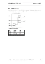
6
Commissioning and optimisation of the switching time
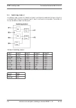
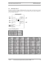
First, the inputs, outputs and the supply voltage for SPEEDY must be wired. When doing this,
please note that the inputs feature optocouplers and a separate GND input.
Then set the required switching mode with the rotary coding switch. If optimisation has not yet
been carried out, the overexcitation time should be set to the minimum value (1 ms).
When all preparations are complete, you can connect the supply voltage to SPEEDY.
For optimisation, the time of the overvoltage pulse can now be incremented step by step until no
further improvement of the switching time is reached.
ATTENTION:
Increasing the pulse time further does not have any positive effect and
simply unnecessarily loads the switching elements.
Note:
The switch-off delay can be reduced without affecting the switch-on delay by reducing the hol-
ding voltage (e. g. 12V instead of 24V).
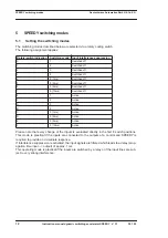
6.1
Recovery times of SPEEDY
The overexcitation voltage of 100 V is generated internally by SPEEDY and buffered in a capac-
itor. The capacitor is partially discharged when a pulse is issued and a "recovery time" is required
until the capacitor has fully recharged. This recovery time is specified in the table below:
Current (mA)
1ms-pulse
2ms-pulse
5ms-pulse
10ms-pulse
0
0 ms
0 ms
0 ms
0 ms
100
1 ms
2 ms
6 ms
13 ms
200
2 ms
4 ms
12 ms
26 ms
300
2 ms
5 ms
17 ms
39 ms
400
3 ms
7 ms
23 ms
52 ms
500
3 ms
9 ms
29 ms
65 ms
600
4 ms
11 ms
35 ms
78 ms
700
4 ms
12 ms
41 ms
91 ms
800
5 ms
14 ms
47 ms
104 ms
900
5 ms
15 ms
52 ms
117 ms
1000
6 ms
17 ms
58 ms
130 ms
1500
28 ms
60 ms
117 ms
170 ms
2000
34 ms
70 ms
130 ms
180 ms
3000
50 ms
94 ms
160 ms
200 ms
Please note that the recovery time always applies to both outputs, i. e. if both outputs are
switched simultaneously, the total of the two output currents must be allowed for as the current in
the table.
If both outputs are switched time-delayed, only the time between the switch-off edge of the first
output’s over-current impulse and the switch-on edge of the next output has to be taken into con-
sideration as the recovery time.
Summary of Contents for SPEEDY Series
Page 2: ...Handbuch Art Nr V3140E...
Page 22: ......


