


Technical details
Deutschmann Automation GmbH & Co. KG
44
Instruction manual ROTARNOCK 100 V. 3.6
4.12.20
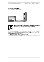
8.4 Specification of the output drivers
The outputs used in the ROTARNOCK are short-circuit-proof and can drive maximum 700 mA
per output at normal ambient temperature.
If more than 700 mA per output are required it is possible to interconnect several outputs.
If several outputs are interconnected, the switch-on and switch-off points in the ROTARNOCK
must be programmed absolutely identically since, otherwise, the short-circuit monitor responds.
In the event of a sustained short circuit or an overload (up to max. 1 A for a short period of time),
the corresponding outputs are deactivated and a corresponding error message is presented on
the display.
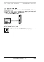
When switching inductances (coils, valves) free-running diodes are to be
placed directly at the inductances (see chapter "EMC Directives for prod-
ucts of DEUTSCHMANN AUTOMATION" on page 11).
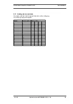
8.5 Estimation of the cycle time
Basic cycle time
Now depending on the configuration the following cycle times have to be added to this basic
cycle time:
Logic active:
450
μ
s
PROFIBUS:
150
μ
s
DICNET:
40
μ
s
Encoder monitoring active: 10
μ
s
Direction cams active:
60
μ
s
So for instance for a ROTARNOCK 100 with PROFIBUS, bitwise idle time and with cams on the
first 16 outputs an approximate cycle time of 225
μ
s (basic cycle time) + 150
μ
s (PROFIBUS) =
375
μ
s is determined.
8.6 Switching accuracy of the Deutschmann cam controls
The accuracy of cam controls is influenced by four parameters:
1) Switching delay (SV)
This time is constant and results from the computing time required by the cam control from
read-in of the encoder value to setting the output driver.
2) Repeat accuracy (WG)
This tolerance band results from asynchronous sampling of the encoder. Ideally, the encoder
is scanned directly after a change. Under worst-case condition, the encoder value changes
directly after read-out of the cam control.
w/o idle time
blockwise
idle time
bitwise
idle time
blockwise
I/O-idle time
bitweise
I/O-idle time
output 1 - 8
100
μ
s
130
μ
s
165
μ
s
135
μ
s
190
μ
s
output 9 - 16
110
μ
s
145
μ
s
225
μ
s
165
μ
s
270
μ
s
output 17 - 24
120
μ
s
160
μ
s
285
μ
s
195
μ
s
350
μ
s
output 25 - 32
130
μ
s
175
μ
s
345
μ
s
225
μ
s
430
μ
s
output 33 - 40
140
μ
s
190
μ
s
405
μ
s
255
μ
s
510
μ
s
output 41 - 48
150
μ
s
205
μ
s
465
μ
s
285
μ
s
590
μ
s
Summary of Contents for ROTARNOCK 100
Page 2: ...Manual Art No V3408E...
Page 4: ...Deutschmann Automation GmbH Co KG 4 Instruction manual ROTARNOCK 100 V 3 6 4 12 20...
Page 57: ......
Page 58: ......


