19
v4.2
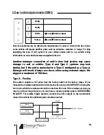
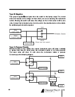
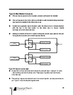
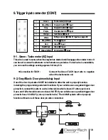
9. Trigger input connector (CON 7)
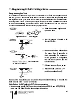
This wire is used to sense when the engine has started and disengages the starter motor. It
can be set to sense the alternator or tachometer as per below. If a tach wire is unavailable,
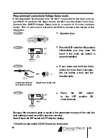
you can use the voltage sensing approach of step 9-6.
◆
Connection for TACH :
Connect the Green TACH input wire to negative
side of the tachometer coil.
9-1 . Green : Tachometer (AC) Input
➀
➁
➂
➃
➄
➅
➆
➇
➈
➉
Green
Gray/Black
Gray
Purple
Orange
White
Gray/White
Red
Red/Black
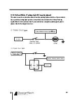
Yellow/White
Tachometer(AC) Input
Doorpin Switch Input
Doorpin Switch Input
Hoodpin Switch Input
foot Brake Input
Voltage sense IGN #1 Input see page 26
Trunk Input
Glow Input
Glow Input
Parking light Input
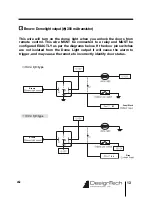
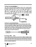
9-2. Gray/Black : Door pin switch Input
One of the door input wires MUST be installed to allow the unit to properly function,
including the programming and alarm functions. If your vehicle uses a negative trigger door
pin switch, connect this wire to a wire in the vehicle which shows 0 V when any door is
Open, and 12V when all doors are closed. NOTE: If your vehicle uses a positive trigger door
pin switch see “#3 GRAY (+) door pin switch wire.” The AirWolf system will not properly
function without one of these door pin wires connected.
B
rown (CON2 #12)
B
rown (CON2 #12)
dome light
dome light
o utput
o utput
G
ray / B lack
G
ray / Black
ground
ground
Summary of Contents for AirWolf
Page 1: ......
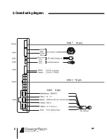
Page 6: ...6 v4 2 2 Overallwiringdiagram ...
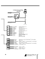
Page 7: ...7 v4 2 ...
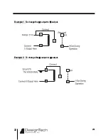
Page 32: ...32 v4 2 Example 1 To change the output to output Example 2 To change the output to output ...
Page 33: ...33 v4 2 MEMO ...
Page 34: ...34 v4 2 MEMO ...
Page 35: ...35 v4 2 MEMO ...
Page 36: ......

