


63 69 149 D3561
D3561
.
076.01.07
.
02 02.2017
72
Dentsply Sirona
6 Overview of modules and boards
Service Manual Sinius / Sinius CS / Sinius TS
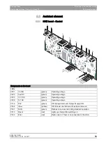
6.3 Dentist element
båÖäáëÜ
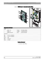
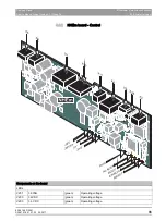
6.3.6
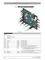
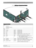
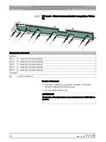
HAP2 board - Baseboard user interface
X17
X10
X11
36V
RESET
+5V
+5V_REG
BL_PWM
SD
KEYBO
ARD
RU
N
ERR
OR
NAND_NOR
CAN
SCOM
BA
CKLIGHT
ANY KEY
PRESSED
+3,3V
HAP2
HAP2
X15
X15
JUMP1T
esmode
JUMP2 Deb
ug
X13
X10
X1
X3
X4
JUMP3
X14
X14
X13
X10
X1
X3
X2
X2
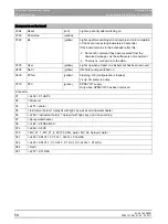
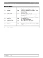
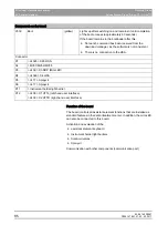
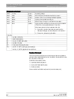
Components on the board
Switch
S1
Erase key
Development purposes
S2
Reset key
LEDs
V201
36V DC
(green)
Operating voltage
V202
5V reg
(green)
Operating voltage
V313
5V
(green)
Operating voltage
V209
3.3V
(green)
Operating voltage
V807
Run
(green)
Flashes once per second when WinCE is running.
V302
Reset
(red)
Lights up when the processor reset is active.
V808
Error
(red)
● 1x Non-correctable ECC error detected during boot
process and defective block labeled
● 2x Correctable ECC errors detected during boot process
V707
BL PWM
(yellow)
Lights up when the backlight is triggered.
V708
Backlight
(yellow)
Lights up when the backlight output is supplying voltage
V805
Any key pressed
(yellow)
Lights up when a key is pressed on the keyboard.
Hardware-controlled (development phase).


