Dentsply Sirona inEos X5 Operating Instructions Manual Download Page 30

6 Initial startup
6.5 Calibrating the inEos X5 camera

Dentsply Sirona

Operating Instructions inEos X5

30

64 17 096 D3586

D3586.201.01.11.02    07.2018

6.5

Calibrating the inEos X5 camera

IMPORTANT

Calibrating the system

The calibration of the inEos X5 camera is only required if you use
ATLANTIS-FLO-S scanbodies in order to design single-piece directly
screwed suprastructures and which can be manufactured at infiniDent
or to transmit the scanned models to Dentsply-Sirona-ATLANTIS
central manufacturing for design and manufacturing purposes.

ü

The inEos X5 is switched on.

ü

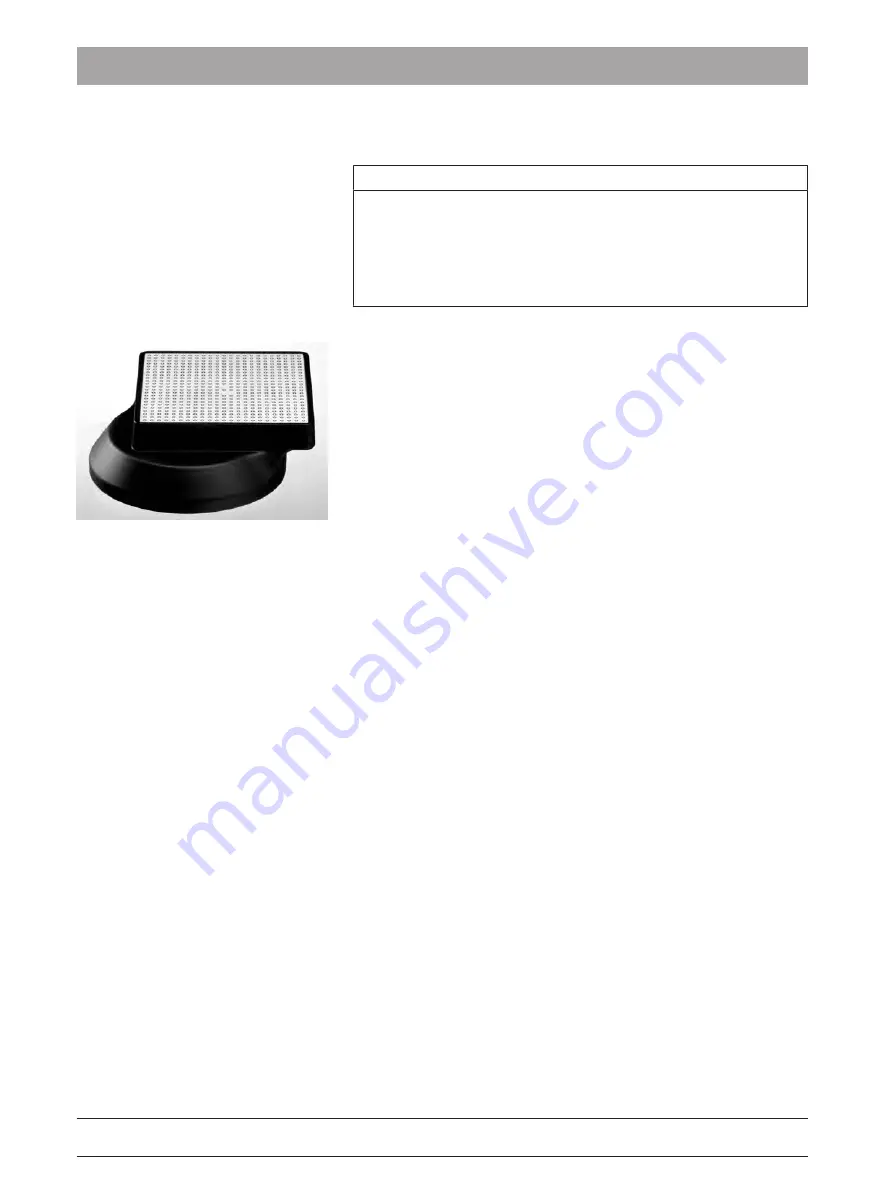
The optionally available calibration set inEos X5 (REF 6483759) is
available.

ü

You have restarted the software.

1.

Click the 

"Devices" button in the system menu.

2.

Click on 

"inEos X5".

Ä

A selection menu opens.

3.

Click on the 

"Calibrate Camera" button.

Ä

The calibration dialog opens.

4.

Once prompted, position the calibration set on the rotary plate as
shown in the software.

5.

Start the calibration process.

Ä

The unit is calibrated.

Ä

Depending on the ambient temperature, the camera optical
system may need some time to warm up. This is required in
order to achieve maximum precision.

6.

Once the calibration is complete, the calibration protocol can be
saved in PDF format.

7.

Restart the software.

Summary of Contents for inEos X5

Page 1: ...New as of 07 2018 inEos X5 Operating Instructions English...

Page 2: ...ntenance and repair 9 3 1 5 Modifications to the product 9 3 1 6 Accessories 10 3 1 7 In case of damage 10 3 2 Blue light radiation UV 11 3 3 To be taken into account during automatic operation 12 3 4...

Page 3: ...tching the unit on and starting the software 29 6 4 Calibrating the motor arm 29 6 5 Calibrating the inEos X5 camera 30 6 6 Updating the firmware 31 7 Controls and displays 32 7 1 Controls on the inEo...

Page 4: ...ng a free detail scan 45 9 5 Rotational scans 46 9 5 1 Preparing the optical impression 47 9 5 2 Taking a rotational scan 47 9 6 Acquiring a buccal registration 48 9 7 Scanbody scans for scanning with...

Page 5: ...ank you for purchasing your inEos X5 from Sirona Improper use and handling can create hazards and cause damage Please read and follow these operating instructions carefully and Always keep them within...

Page 6: ...nd material damage please observe the warning and safety information provided in these operating instructions Such information is highlighted as follows DANGER An imminent danger that could result in...

Page 7: ...vidual action step Prompts you to do something See Formats and symbols used 7 Identifies a reference to another text passage and specifies its page number List Designates a list Command menu item Indi...

Page 8: ...11 02 07 2018 Symbols on the packaging Take note of the following symbols on the packaging Top Protect from moisture Fragile handle with care Do not stack 40 70 Temperature during storage and transpor...

Page 9: ...ctions given in the present operating instructions 3 1 3 Connection of external equipment If any equipment not approved by Sirona is connected it must comply with the applicable standards EN 60 950 fo...

Page 10: ...a accessories or third party accessories expressly approved by Dentsply Sirona In particular only the power cable also supplied or the corresponding original spare part may be used with the unit The u...

Page 11: ...at the lamp during operation as eye damage can result NOTE No reflective objects in the working area Do not bring any reflective objects into the working area of the lamp WARNING Risk of injury for th...

Page 12: ...ects and or body parts on the work plate shaded area during automatic operation 3 4 Intended use This system is used for 3D digitization of single tooth or complete jaw models and impressions This uni...

Page 13: ...are connected to this unit must also bear the CE mark These products must be tested according to the applicable standards Examples of CE mark for connected products EN 60950 1992 A1 1993 A2 1993 A3 19...

Page 14: ...ly unit The unit is connected to a PC via a USB port The PC must fulfill the minimum requirements see Chapter on System requirements The PC serves both for controlling the inEos X5 and for displaying...

Page 15: ...17 096 D3586 D3586 201 01 11 02 07 2018 15 Rear side M 24 V USB 2 0 M6324649 Model No D3586 Merial No 00106 REF 6324649 Sirona Dental Systems GmbH Fabrikstr 31 D 64625 Bensheim Made in Germany 2013 S0...

Page 16: ...use Pollution degree 2 Temperature 10 C 35 C 50 F 95 F Relative humidity 30 75 Air pressure 700hPa 1060hPa Operating altitude 2 000m Transport and storage conditions Temperature 40 C 70 C 40 F 158 F R...

Page 17: ...os X5 is hereinafter referred to as UNIT 4 5 1 Electromagnetic emission The UNIT is intended for operation in the electromagnetic environment specified below The customer or user of the UNIT should ma...

Page 18: ...mode voltage 2 kV common mode voltage The quality of the line power supply should be that of a typical commer cial or hospital environment Voltage dips short interruptions and variations of the power...

Page 19: ...ent bearing the following graphic symbol Remark 1 The higher frequency range applies at 80 MHz and 800 MHz Remark 2 These guidelines may not be applicable in all cases The propagation of electromagnet...

Page 20: ...ssion frequency m 150 kHz to 80 MHz 80 MHz to 800 MHz 800 MHz to 2 5 GHz d 1 2 P d 1 2 P d 2 3 P 0 01 0 12 0 12 0 23 0 1 0 38 0 38 0 73 1 1 2 1 2 2 3 10 3 8 3 8 7 3 100 12 12 23 For transmitters whose...

Page 21: ...onsignment is complete 2 Check whether the product shows any visible signs of damage NOTE Damage during transport If the product was damaged during transport please contact your carrying agent If retu...

Page 22: ...ion site Make sure that the specified operating conditions are observed see section Technical data 16 NOTE Install inEos X5 in a protected area 3D image acquisition may be adversely affected by bright...

Page 23: ...4 17 096 D3586 D3586 201 01 11 02 07 2018 23 6 Initial startup 6 1 Putting the inLab 4 PC into operation 6 1 1 Startup prerequisites 6 1 1 1 Required accessories Supplied parts inLab PC with power cab...

Page 24: ...ope of supply CAUTION Image may not display Please note the required minimum monitor resolution of 1280 x 1024 at 70Hz Please refer to the technical documentation of the monitor for the correct resolu...

Page 25: ...xactly in order to successfully perform start up of your device You must install the user software prior to connecting the device to the PC F E D C B A inEos X5 A USB license stick B USB for inEos X5...

Page 26: ...perate this PC in a network LAN or Internet damage may be caused by software viruses Activate the Automatic Updates function of Microsoft Security Essentials Activate the Automatic Updates function of...

Page 27: ...rt the DVD in the DVD drive The setup program starts automatically 2 If this is not the case run the Setup exe file in the root directory of the DVD The installation wizard opens 3 Click on the OK but...

Page 28: ...ort of your PC via the interface cable included in the scope of supply 6 3 2 Connecting the unit to the power supply M 24 V USB 2 0 M6324649 Model No D3586 Merial No 00106 REF 6324649 Sirona Dental Sy...

Page 29: ...re at the PC via the Windows start menu 6 4 Calibrating the motor arm IMPORTANT Calibrating the system Following installation of the inEos X5 it is recommended that you perform an axis calibration wit...

Page 30: ...manufacturing purposes The inEos X5 is switched on The optionally available calibration set inEos X5 REF 6483759 is available You have restarted the software 1 Click the Devices button in the system m...

Page 31: ...witch inEos X5 off at the main switch 5 Then simply proceed as prompted by the inLab software The inEos X5 firmware will be updated The percentage of completed progress is displayed IMPORTANT Do not d...

Page 32: ...d displays 7 1 Controls on the inEos X5 inEos X5 features the following controls A Start key B CC CAUTION Stopping motor movements By pressing and holding the Start key A all movements of the motor ar...

Page 33: ...tuated LED lights up yellow An automatic acquisition process has been started the arm is already moving or is about to start moving CAUTION Risk of injury Do not place any part of your body either who...

Page 34: ...nit to the operating site from a cold environment condensation may form and result in a short circuit Install the unit at room temperature Wait until the unit has reached room temperature and is absol...

Page 35: ...single restorations without consideration of the proximal contacts or the antagonist Scanbody scan For the measurement of one or more inPost scanbodies Tip You can execute several scan methods in sequ...

Page 36: ...nts covered with Optispray When using scan wax When measuring scanbodies When capturing silicon impression trays with several multi colored impression materials inEos X5 captures these situations usin...

Page 37: ...The buccal side of the impression must always point toward the retaining screw In the case of quadrant impressions place the impression tray in the central holder position in such a way that the last...

Page 38: ...s from Complete to Reduced For all future cases the reconstruction mode set as the default in each case is selected in each image catalog However this can be adjusted separately at any time The mode c...

Page 39: ...ot switch REF 63 10 449 to start and end scanning processes in the respective scanning mode Plug the connector of the foot switch into the matching socket USB port of your PC 9 2 Starting the unit sta...

Page 40: ...ly the ones involved here All of the gaps in the digital model are closed in the scanned areas via the intelligent gap closing technique All other areas of the model are scanned with a lower degree of...

Page 41: ...n in the software If you have selected the area scanning scan mode the inEos X5 automatically generates five to six scans from the occlusal aspect On completion of the overview scans the model preview...

Page 42: ...be released by clicking the mouse 1 Position the virtual model so that the area of interest is well visible 2 Start the automatic detail scan by double clicking on the area of interest The inEos X5 po...

Page 43: ...al impression You have selected the desired image catalog lower jaw upper jaw etc Tip Take special care to select the right image catalog for detail scans 1 Fasten the model to the supplied model hold...

Page 44: ...preview An individual scan is taken with each release Capture Auto 1 Select the Capture Auto mode in the Scan menu or Alternatively you can click on the Start button of the inEos X5 The crosshairs in...

Page 45: ...del on the shifting plate by up to 40 NOTE The new image must overlap approximately 30 50 of the previous image 5 Repeat step 4 until all of the required scans have been taken 9 4 4 Taking a free deta...

Page 46: ...dual stump scan slanted For scanning all standard individual stumps Tip Change the angle for the individual stump scans for the scanning of heavily chamfered stumps or for scanning abutments by moving...

Page 47: ...nning more than one object simultaneously place the model holders in the outer positions of the model holding plate The articulating arm moves to the loading position 4 Fasten the model holding plate...

Page 48: ...ric jaw relation and an exposure taken that records both jaws at the same time Tip The model can be left in the articulator Alternatively it is recommended to fasten the model e g with wax and manuall...

Page 49: ...ch Place an object as thick as a finger e g a felt tip pen in the scan element opening in the operating mode Operating state LED Test result The operating state LED changes from green to red Nominal s...

Page 50: ...t the main switch The power LED lights up green Press and hold the Start key Operating state LED Test result The operating state LED changes from green to red Nominal state Stop function guaranteed Th...

Page 51: ...quired you can clean the optical surfaces The unit is switched on at the main switch 1 Switch to the scan phase in the inLab software 2 Select Capture Free 3 Place a sheet of paper on the work surface...

Page 52: ...ball joint model holder or the articulated arm of the inEos X5 during free or automatic scans Magnetic pot D30 8x for scanning individual stumps Please use Blue filling material Magnetic pot D50 2x f...

Page 53: ...11 02 07 2018 53 12 1 Using the articulator plate 1 Use the adjusting screw to set the height of the articulator plate in such a way that the model lies horizontally in the articulator on the articul...

Page 54: ...itiate return of the electrical device please send a disposal request to enretec GmbH You have the following options here Use the Returning an electrical device button under the eom menu item on the e...

Page 55: ......

Page 56: ...be required due to technical improvements Sirona Dental Systems GmbH Sprache englisch Printed in Germany D3586 201 01 11 02 07 2018 Nr 125 746 Sirona Dental Systems GmbH Fabrikstr 31 64625 Bensheim G...

Reviews: