14
DVD-3800BDCI
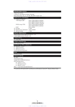
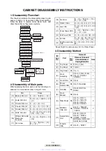
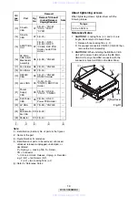
(1) Identification (location) No. of parts in the figures
(3) Figure Number for reference
(4) Identification of parts to be removed, unhooked,
unlocked, released, unplugged, unclamped, or
desoldered.
P = Spring, L = Locking Tab, S = Screw,
CN = Connector
* = Unhook, Unlock, Release, Unplug, or Desolder
e.g. 2(S-2) = two Screws (S-2),
2(L-2) = two Locking Tabs (L-2)
(5) Refer to “Reference Notes.”
About tightening screws
When tightening screws, tighten them with the
following torque.
Reference Notes
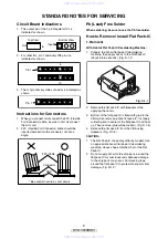
1.
CAUTION 1:
Locking Tabs (L-1) and (L-2) are
fragile. Be careful not to break them.
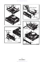
1) Release three Locking Tabs (L-2).
2) Disconnect connectors CN2001, CN4002, then
remove the Front Assembly.
2.
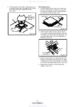
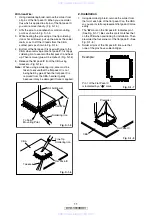
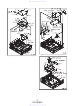
CAUTION 2:
When installing the BE Main CBA
Unit with a screw, hold and press the BE Main
CBA Unit to align the HDMI connector with the
connector’s hole for HDMI on the Rear Panel.
[13]
F-Audio
CBA
D7
3(S-22), *CN061,
*CN10, *CX201,
*CY281
---
[14]
S-Audio
CBA
D7 3(S-23)
---
[15]
ADSP CBA
Unit
D7
2(S-24), (S-25),
4(S-26), 2(S-27),
*CX876, DSP PCB
Holder, Audio PCB
Holder
---
[16]
FE Main
CBA & BD
Mechanism
Assembly
D8 4(S-28), *CN2601
---
[17] Fan Holder
D8 2(S-29), *CN2500
---
[18] Fan Motor
D8 2(S-30)
---
[19]
RS232C
CBA
D9
3(S-31), *CN2551,
RS232C Holder
---
[20] Jack CBA
D9
(S-32), (S-33),
*CN2730, BNC PCB
Holder
---
[21]
Power
Supply
CBA
D9
2(S-34), 2(S-35),
*CN101, *CN2501
---
[22]
Sub Power
CBA
D9
3(S-36), 2(S-37),
Power PCB Holder
---
[23] AV CBA
D9 7(S-38), *CN2503
---
[24]
Sub
Microcontro
ller CBA
D10 4(S-39)
---
[25] Pedestal
D10 3(S-40)
---
↓
(1)
↓
(2)
↓
(3)
↓
(4)
↓
(5)
ID/
Loc.
No.
Part
Removal
Fig.
No.
Remove/*Unhook/
Unlock/Release/
Unplug/Desolder
Note
Torque
0.45 ± 0.05 N·m
(S-2)
(S-2)
(S-1)
(S-1)
(S-1)
(S-1)
(S-1)
Fig. D1
[1] Top Cover
www. xiaoyu163. com
QQ 376315150
9
9
2
8
9
4
2
9
8
TEL 13942296513
9
9
2
8
9
4
2
9
8
0
5
1
5
1
3
6
7
3
Q
Q
TEL 13942296513 QQ 376315150 892498299
TEL 13942296513 QQ 376315150 892498299


