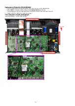
3. RADIATOR ASSY
Proceeding : TOP COVER
→
DIGITAL PCB
→
RADIATOR ASSY
(1) Remove the screws.
(2) Remove the screws.
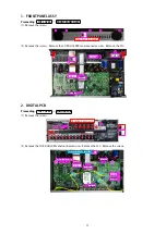
4. POWER PCB
Proceeding : TOP COVER
→
POWER PCB
See "EXPLODED VIEW" for instructions on removing the POWER PCB.
5. REGULATOR PCB
Proceeding : TOP COVER
→
REGULATOR PCB
See "EXPLODED VIEW" for instructions on removing the REGULATOR PCB.
6. TRANS POWER
Proceeding : TOP COVER
→
TRANS POWER
See "EXPLODED VIEW" for instructions on removing the transformer (TRANS).
Shooting direction: A
x5
x12
x2
x2
x2
x4
CN502
CN104
18
Summary of Contents for AVR-S710W
Page 8: ...8 Personal notes ...
Page 144: ...NJU72340AFH3 DIGITAL_ANALOG IC821 NJU72340A Terminal Functions 144 ...
Page 147: ...2 FL DISPLAY FLD 018BT021GINK FRONT FL101 PIN CONNECTION GRID ASSIGNMENT 147 ...
Page 148: ...ANODE CONNECTION 148 ...
Page 168: ...EXPLODED REF No Part No Part Name Remarks Q ty New Ver S14 nsp SCREW CTW3 6JR VTW3 6JR 2 20 ...

