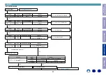
Proceeding :
TOP COVER
→
FRONT PANEL ASSY
→
RADIATOR ASSY
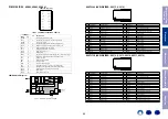
(1) Remove the screws. Remove the STYLE PIN and connectors.
(2) Remove the connector.
2. RADIATOR ASSY
x2
x1
N5821
N5842
N5834
N5833
L-AMP CONNECT
R-AMP CONNECT
STYLE PIN
H2L
PURPLE
H1L
YELLOW
SBL GRA
Y
SL
BROWN
FL RED
C
BLUE
FR RED
SR
BROWN
SBR GRA
Y
H1R
YELLOW
H2R
PURPLE
L-AMP CONNECT
R-AMP CONNECT
STYLE PIN
Proceeding :
TOP COVER
→
DIGITAL PCB
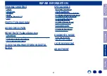
(1) Remove the screws.
(2) Remove the STYLE PINs and connectors.
Remove the FFC. Remove the screws.
3. DIGITAL PCB
↓
Shooting direction: A
↓
↑
Shooting direction: C
↑
↑
Shooting direction: D
↑
x2
x2
x5
x6
x4
STYLE PIN
N6201
N6012
N3403
N9019
N9016 N9018 N9017
FFC
N8001
STYLE PIN
Before Servicing
This Unit
Electrical
Mechanical
Repair Information
Updating
78


