background image

Original instructions 


 OPERATIONS MANUAL  

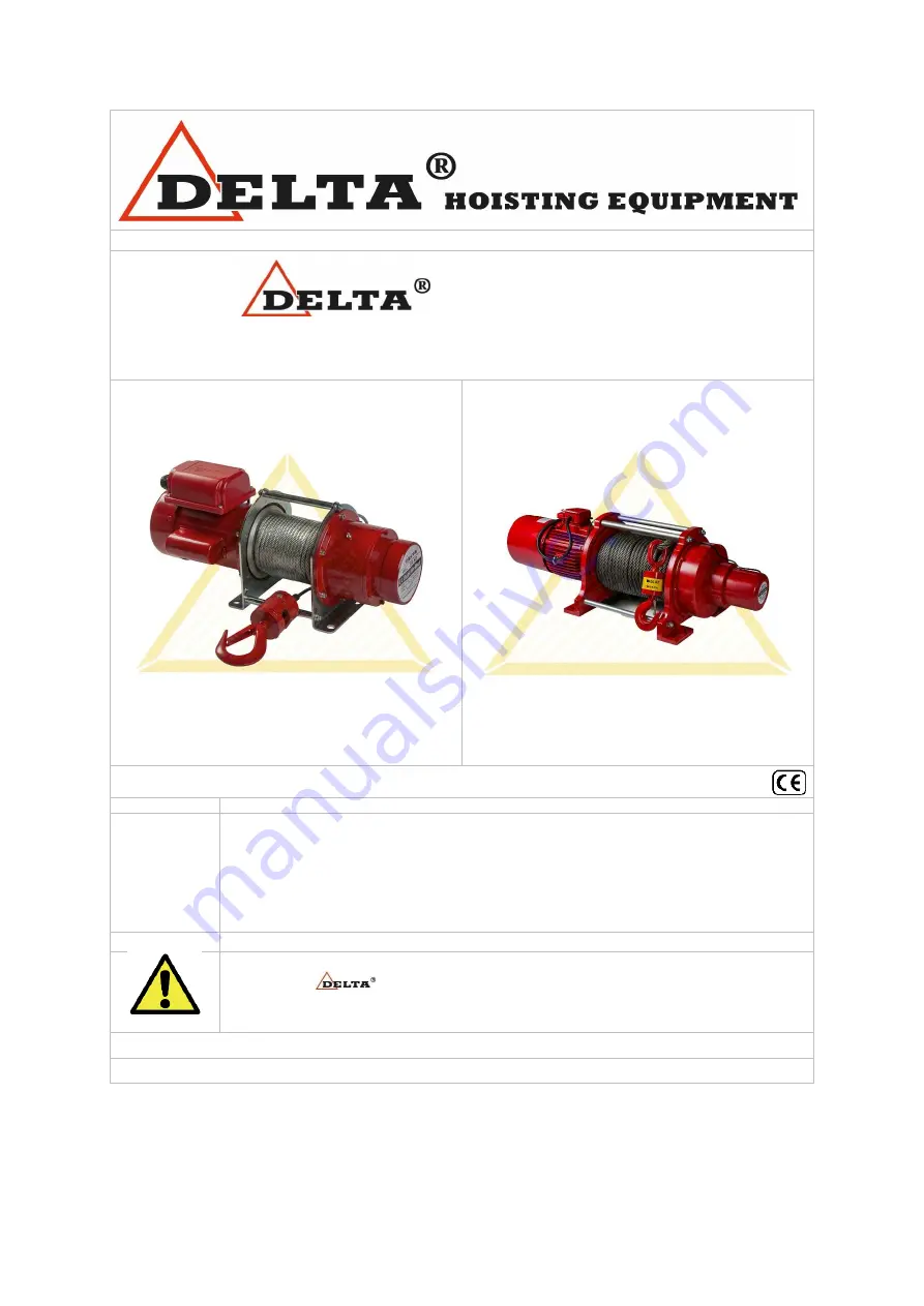
ELECTRIC WINCHES 230/400 VOLT


 [CP.0.DPS / DPT series] 


CP.0.DPS SERIES 230 VOLT 


CP.0.DPT SERIES 400 VOLT


NOTE:


All of the information reported herein is based on data available at the moment of 
printing. We reserve the right to modify our own products at any moment without 
notice.  Please  read  the  operating  instructions  carefully  before  using  this  product. 
Always keep a copy of this instruction manual at hand. Failure to read and comply 
with  the  contents  of  this  manual  can  result  in  serious  body  injury  or  death,  and 
property damage.  


THIS IS THE SAFETY ALERT SYMBOL. WHEN YOU SEE THIS SYMBOL 
ON  YOUR 


PRODUCTS  OR  IN  THIS  MANUAL,  BE  ALERT  FOR 

DANGEROUS  SITUATIONS.    FOLLOW  RECOMMENDED  AND  SAFE 
OPERATING INSTRUCTIONS AT ALL TIMES.


If any doubt remains, please contact your supplier.


Summary of Contents for CP.0.DPS Series

Page 1: ...hout notice Please read the operating instructions carefully before using this product Always keep a copy of this instruction manual at hand Failure to read and comply with the contents of this manual can result in serious body injury or death and property damage THIS IS THE SAFETY ALERT SYMBOL WHEN YOU SEE THIS SYMBOL ON YOUR PRODUCTS OR IN THIS MANUAL BE ALERT FOR DANGEROUS SITUATIONS FOLLOW REC...

Page 2: ...t the rated capacity of electric winch Before installing make sure that electric pulling winch wire rope and other components are visibly in good condition After installing periodically inspect these to make sure that this is kept If not please contact your supplier or another professional The ambient temperature of electric winch and load must be between 10 C 40 degrees C A technical study by a p...

Page 3: ...ification Page 10 3 4 2 Fem Classification Page 10 4 Safe operation Page 11 4 1 Declaration Page 11 4 2 Install and test Page 11 4 3 Test before operation Page 11 4 4 Inspection Page 11 5 Installation Page 12 5 1 Pre installation check Page 12 5 2 Mounting holes of electric winch Page 13 5 3 Initial lubrication Page 13 5 4 Connection to electrical supply Page 13 5 5 Starting Page 13 6 Operation Pa...

Page 4: ...ned for pulling load which has to be used under normal working conditions It is strictly forbidden to pull or lift persons The manual use the below markings to identify the level and grade of danger DANGER Very dangerous situation if the danger is not avoided it will cause death or serious injury WARNING Potential dangerous situations means if the warning is not heeded it can cause death or seriou...

Page 5: ...oles Make sure that bolt and nuts are tightly secured The bottom hook must be complete and in good condition so assure that it has no deformation or loose components Safety lock mechanism must be in place CAUTION Check the winch for correct functioning the brake needs to hold the pulled load CAUTION When the temperate is below 0 C check the brake at all times 2 3 Warnings during operation WARNING ...

Page 6: ... and intervene on the winch 2 5 Inspection and maintenance CAUTION Professionals must inspect and maintain the winch regularly otherwise please contact your dealer to inspect and service the winch WARNING The wire rope cannot be repaired it must be replaced when damage or wear is severe WARNING It is forbidden to use the winch which has any problems or obvious signs of damage Also during maintenan...

Page 7: ...8 43 43 68 Standard Control cable m 2 2 2 2 Operation voltage single phase 400V 400V 400V 400V Cycle hz 50 60 Hz 50 60 Hz 50 60 Hz 50 60 Hz Power output watt 750 1500 2250 3750 Pulling speed m min 14 1 18 9 12 9 17 4 Wire rope diameter 7 8 10 12 Duty rate ED 40 40 40 40 No of starts per hour 240 240 240 240 Housing protection IP IP 44 IP 44 IP 44 IP 54 Control protection IP 65 IP 65 IP 65 IP 65 Cl...

Page 8: ...8 3 2 2 electric pulling winch capacity per layer ...

Page 9: ...279 164 261 201 49 41 155 224 7 DPS 500 246 272 180 285 310 49 41 260 305 8 DPT 30075 160 279 164 261 201 49 41 155 224 7 DPT 30151 246 272 180 365 310 49 41 260 305 8 DPT 30375 340 383 360 365 400 39 30 350 510 14 DPT 30750 378 524 436 520 590 39 30 540 525 14 85 DPT 31500 378 580 436 520 590 45 35 540 525 14 85 DPT 34000 510 694 436 520 590 55 38 540 660 14 85 ...

Page 10: ...able and steel cable with hook Complies with the Machinery Directive 2006 42 EC Note without overload protection from 1 ton digital overload protection optional 3 4 Machine classification and period of use Identify the normal use of the product in order to ensure the safety and service life electric winch is suitable for the ISO JIS and FEM classification 3 4 1 ISO JIS Classification Average Daily...

Page 11: ...tion Before operation of the winch always test it for correct functioning without load If it runs normally winch may be used with load Always check the brake by performing a small test where the load is suspended full capacity the brake must keep the load 4 4 Inspection To ensure continuous and satisfied functioning of the electric pulling winch it must be inspected on a regular basis Let professi...

Page 12: ...ng winch CAUTION Inspect the engine chamber it needs to be clean and dry Also make sure that the electric winch is protected against any form of humidity CAUTION Make sure that the winch and steel wire is free of obstructions The following environmental conditions will result to winch failures Low temperatures below 10 C High temperatures above 40 C In organic chemical or explosive atmospheres In ...

Page 13: ...vant Lubrication Heavy Service daily Normal weekly Infrequent Monthly 5 4 Connection to electrical supply An adequate electricity supply system is required along the total length of travel where appropriate The supply voltage and frequency at which the winch operates is marked on the motor rating plate It is Imperative to check before connecting the unit that these figures correspond with those of...

Page 14: ...oad and make sure that a generous safety factor is included DANGER Always make sure that the load does not exceed the rated capacity DANGER For points fitted with warning alarm it should be sounded each time before use travelling and intermittently during travel particularly when operator or other personnel is approached If not the user is responsible to inform everyone when winch is operated DANG...

Page 15: ...neuverer without attempting any further actions Immediately set up a safety perimeter around the winch and the load to prevent access by any unauthorized persons Call in the necessary personnel to remove the load and intervene on the winch WARNING Stop operation if there is any abnormal noise or vibrations in the gear box WARNING Do not connect the with the grounding of the welding machine WARNING...

Page 16: ...se contact your dealer CAUTION Forbidden to use the winch which is under maintenance service CAUTION If any abnormal behaviour of the winch is found before during and after operation please contact a professional and inspect the winch CAUTION Don t leave the winch suspended or store it with suspended load CAUTION Clean the winch from any kind of dirt CAUTION Store the winch in a place where it is ...

Page 17: ...ys leave a minimum of 3 wraps of wire rope around the drum to support the rated load 7 4 Initial lubrication Winches do not require the initial lubrication but this should be checked on a regular basis The re lubrication interval depends on the service and is recommended as following use this oil or a equilavant Model DPS 200 DPS 250 DPS 300 DPS 500 DPT 30075 Lubricant of gearbox Recommended SHELL...

Page 18: ...ck push button contacts and wires Hook will release lower pull raise but will not pull raise Overload Reduce loading to rated load of winch as shown on nameplate Winch electrical circuit open Check for loose connections See that necessary jumper wires are properly installed on contactor Contactor assembly not functioning See that necessary jumper wires are properly installed Verify that the contac...

Page 19: ... connections Abnormal noise from wirerope drum Lake of lubrication worn wire rope drum Check all wiring for loose connections DANGER Emergency procedure In the event of a blocked steel wire or any other malfunction of electric pulling winch immediately stop the maneuverer without attempting any further actions Immediately set up a safety perimeter around the winch and the load to prevent access by...

Page 20: ... Plastic box rack 25 Bearing 48 Base of plastic tube 6 Screw 26 Bearing 49 Plastic tube 7 Bolt 27 Base of gear component 50 Switch connector 8 Bearing 28 Bearing 51 Fix plate 8 1 Link 29 Bearing 52 Fix plate 9 Main body motor 30 Gear box 53 Screw 10 Bolt 31 Screw 54 Screw 11 Drum 32 Base of brake coil 55 Switch button cover 12 Fix bar 33 Brake coil 56 Screw 13 Screw 34 Spring 13 1 Fix bar 35 Screw...

Page 21: ...21 CP 0 DPS 200 Control Circuit ...

Page 22: ...x rack 25 Bearing 48 Base of plastic tube 6 Screw 26 Bearing 49 Plastic tube 7 Bolt 27 Base of gear component 50 Switch connector 8 Bearing 28 Bearing 51 Fix plate 8 1 Link 29 Bearing 52 Fix plate 9 Main body motor 30 Gear box 53 Screw 10 Bolt 31 Screw 54 Screw 11 Drum 32 Base of brake coil 55 Switch button cover 12 Fix bar 33 Brake coil 56 Screw 13 Screw 34 Spring 13 1 Fix bar 35 Screw 14 Bearing...

Page 23: ...23 CP 0 DPS 250 Control Circuit ...

Page 24: ...25 Bearing 48 Base of plastic tube 6 Screw 26 Bearing 49 Plastic tube 7 Bolt 27 Base of gear component 50 Switch connector 8 Bearing 28 Bearing 51 Fix plate 8 1 Link 29 Bearing 52 Fix plate 9 Main body motor 30 Gear box 53 Screw 10 Bolt 31 Screw 54 Screw 11 Drum 32 Base of brake coil 55 Switch button cover 12 Fix bar 33 Brake coil 56 Screw 13 Screw 34 Spring 13 1 Fix bar 35 Screw 14 Bearing 36 Gea...

Page 25: ...25 CP 0 DPS 300 Control Circuit ...

Page 26: ...27 Gear 47 Plastic tube 7 Power cable 28 Bearing 48 Pendant switch 8 Switch cable 29 Key 49 Switches 9 Motor 30 Gear component 50 Fix plate 10 Bolt 30 1 Link 51 Screw 11 Washer 31 Shaft 52 Screw 12 Screw 32 Key 53 Switch cover 13 Main body Motor 33 Bearing 54 Screw 14 Fix bar 34 Oil seal 55 Fix plate 15 Drum 35 Gear box 56 Screw 16 Wire rope 36 Screw 57 Screw 17 Hook 37 Brake Coil 18 R pin 38 Brak...

Page 27: ...27 CP 0 DPS 500 Control Circuit ...

Page 28: ... 25 Bearing 48 Base of plastic tube 6 Screw 26 Bearing 49 Plastic tube 7 Bolt 27 Base of gear component 50 Switch connector 8 Bearing 28 Bearing 51 Fix plate 8 1 Link 29 Bearing 52 Fix plate 9 Main body motor 30 Gear box 53 Screw 10 Bolt 31 Screw 54 Screw 11 Drum 32 Base of brake coil 55 Switch button cover 12 Fix bar 33 Brake coil 56 Screw 13 Screw 34 Spring 13 1 Fix bar 35 Screw 14 Bearing 36 Ge...

Page 29: ...29 CP 0 DPT 30075 Control Circuit ...

Page 30: ... 27 Gear 47 Plastic tube 7 Power cable 28 Bearing 48 Pendant switch 8 Switch cable 29 Key 49 Switches 9 Motor 30 Gear component 50 Fix plate 10 Bolt 30 1 Link 51 Screw 11 Washer 31 Shaft 52 Screw 12 Screw 32 Key 53 Switch cover 13 Main body Motor 33 Bearing 54 Screw 14 Fix bar 34 Oil seal 55 Fix plate 15 Drum 35 Gear box 56 Screw 16 Wire rope 36 Screw 57 Screw 17 Hook 37 Brake Coil 18 R pin 38 Bra...

Page 31: ...31 CP 0 DPT 30151 Control Circuit ...

Page 32: ... 5 Brake component 20 1 Bearing 37 1 Bearing 5 1 Screw 20 2 Bearing 38 Fix bar 6 Spring 21 Bearing 39 Arbor 6 1 Screw 22 Gear 40 Main body of motor 7 Screw 23 Fix pin 41 Screw 8 Brake component 24 spring 42 Bolt 9 Bolt 25 Key 43 Motor 9 1 Bolt 26 Shaft 10 Brake component 27 Screw 11 Brake steel plate 28 Gear box 11 1 Brake component 28 1 Bearing 11 2 Spring 28 2 Bearing 12 Brake steel plate 29 Gea...

Page 33: ...33 CP 0 DPT 30375 Control Circuit ...

Page 34: ... 5 Brake component 20 1 Bearing 37 1 Bearing 5 1 Screw 20 2 Bearing 38 Fix bar 6 Spring 21 Bearing 39 Arbor 6 1 Screw 22 Gear 40 Main body of motor 7 Screw 23 Fix pin 41 Screw 8 Brake component 24 spring 42 Bolt 9 Bolt 25 Key 43 Motor 9 1 Bolt 26 Shaft 10 Brake component 27 Screw 11 Brake steel plate 28 Gear box 11 1 Brake component 28 1 Bearing 11 2 Spring 28 2 Bearing 12 Brake steel plate 29 Gea...

Page 35: ...35 CP 0 DPT 30750 Control Circuit ...

Page 36: ...43 Nut 7 Screw 25 Main body of Gear 44 Motor cover 8 Brake component 25 1 Bearing 9 Brake component 26 Fix Bar 10 Brake steel plate 26 1 Bearing 11 Brake component 27 Drum 12 Brake steel plate 28 Main body of motor 12 1 Fix bar 29 Arbor 13 Brake steel plate 30 Bolt 14 Hexagon brake 31 Motor 15 Hexagon brake disc 32 Brake bracket 16 Base of gear 33 Brake disc 17 Bearing 34 Brake plate 18 Bearing 35...

Page 37: ...37 CP 0 DPT 31500 Control Circuit ...

Page 38: ...43 Nut 7 Screw 25 Main body of Gear 44 Motor cover 8 Brake component 25 1 Bearing 9 Brake component 26 Fix Bar 10 Brake steel plate 26 1 Bearing 11 Brake component 27 Drum 12 Brake steel plate 28 Main body of motor 12 1 Fix bar 29 Arbor 13 Brake steel plate 30 Bolt 14 Hexagon brake 31 Motor 15 Hexagon brake disc 32 Brake bracket 16 Base of gear 33 Brake disc 17 Bearing 34 Brake plate 18 Bearing 35...

Page 39: ...39 CP 0 DPT 34000 Control Circuit ...

Page 40: ...40 9 Derived certificate of test Declaration of CE conformity ...

Page 41: ...41 Address Uiterdijk 6 7 1505 GW Zaandam The Netherlands Typesetting and printing errors reserved All rights reserved No part of this publication may be reproduced without prior written consent of SE O ...

Reviews: