INSTRUCTION
MANUAL
REVISED 6-14-99
PA RT NO. 422-19-651-0042
'Delta International Machinery Corp. 1999
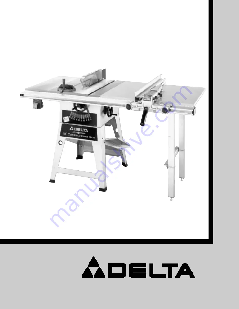
Platinum Edition
10"Contractor s Saw
with 30" Unifence
fi
(Model 36-475)
Page 1: ...INSTRUCTION M A N U A L REVISED 6 14 99 PA RT NO 422 19 651 0042 Delta International Machinery Corp 1999 Platinum Edition 10 Contractor s Saw with 30 Unifencefi Model 36 475...
Page 2: ...ding Instructions 24 120 Volt Single Phase Operation 24 240 Volt Single Phase Operation 25 FASTENING STA N D TO SUPPORTING SURFA C E 25 OPERATING CONTROLS A N D ADJUSTMENTS St arting And Stopping Saw...
Page 3: ...er at the rate for which it was designed 1 0 USE RIGHT TO O L D o n tf o r c et o o lo ra t tachment to do a job for which it was not designed 11 W E A R PROPER APPAREL No loose clothing gloves neckti...
Page 4: ...n r i s k o f i n j u r i e s 1 3 PROVIDE adequate support to the rear and sides of the saw table for wide or long workpieces 1 4 AVOID kickbacks work thrown back toward you by A Keeping blade sharp B...
Page 5: ...he Unifencefi 1 Contractor s Saw 2 Blade Tilting Handwheel 3 Handwheel Lock Knob 4 Blade Guard and Sp l i t t e r Assembly 5 Table Insert 6 Miter Gage 7 Miter Gage Handle 8 Miter Gage Handle Cap 9 Spl...
Page 6: ...el 1 Unifence Body 2 Fence 3 Shelf Support Bracket 4 Front Table Support 5 Table Board 6 Table Legs 2 7 Front Guide Rail 8 Leg Adapter 2 9 Flat Washers 2 1 0 Leveling Screws 2 11 Z Brackets 2 1 2 7 16...
Page 7: ...assembled to the front o fs tand B NOTE The front stand panel will have the saw identity labels facing you Do not completely tighten t h e s tand hardware at this time Also make certain the dust chut...
Page 8: ...lustrates the saw E assembled to the saw s tand B Carefully push down on the top of the saw until t h e s tand legs are positioned firmly on the floor surface and securely tighten all saw and stand mo...
Page 9: ...ng four carriage bolts f l a t washers star washers and hex nuts C NOTE Do not completely tighten the hex nuts a t t h i s t i m e ASSEMBLING M O TO R AND MOTO R MOUNTING PLATE TO S AW W ARNING W H E...
Page 10: ...ut Tighten set screw C against key A in motor shaft 3 Remove wing nut and external tooth lockwasher D Fig 17 and outer cover E from belt and pulley guard G 4 Slide the belt and pulley guard bracket G...
Page 11: ...FT UNTIL Y O U A R E CERTAIN THE E N D BELL J O F THE M O TO R I S B E L O W THE TO P O F THE TABLE SURFACE THEN RE ALIGN THE M O TO R PULLEY TO THE A R B O R PULLEY 9 Assemble the outer cover E Fig 2...
Page 12: ...4 hex head screws B and flat washers Do not completely tighten the two screws B at this time 2 W ith wrenches supplied remove the saw blade from the saw R e f e rt os e c t i o n CHANGING THE S AW BLA...
Page 13: ...and tighten screw H with wrench supplied 8 Fasten the rear of the blade guard and splitter bracket assembly G Fig 30 to the rear splitter mounting bracket using 5 8 c a r r i a g e b o l t J f l a t w...
Page 14: ...33 and 34 If alignment is necessary loosen the screws A Fig 34 align splitter G with the saw blade and tighten two screws A 11 Lower saw blade and insta l ltable insert P F i g 3 5 in the saw table as...
Page 15: ...MBLING SWITCH TO EXTENSION WING 1 Assemble switch A Fig 38 behind the lip of exten sion wing B with 1 4 20 x 3 4 flat head screw C flat washer and locknut 2 Fig 39 illustrates the switch assembled to...
Page 16: ...pward on Z brackets A while tighten ing screws C to eliminate any play 3 Fig 42 illustrates the Z brackets assembled to the saw blade 4 Assemble angle bracket E Fig 43 onto Z bracket A using 1 4 20 x...
Page 17: ...od screws C as shown Assemble r emaining ta b l e l e g t o t h e table in the same manner CAUTION D O N O T OVER TIGHTEN LEG MOUNTING S C R E W S Over tightening screws in particle board may cause th...
Page 18: ...nto foot adapter F i g 4 9 i l l u s t r a t e s t h e f o o t l e v e l i n g assembly on the ta b l e l e g Assemble the remaining foot assembly to the other table leg in the same manner NOTE Height...
Page 19: ...ver tightening screws in particle board may cause them t os t r i p 3 Using a straight edge D Fig 53 make certain the surface of the Unifence table A is level with the saw t able F by adjusting the he...
Page 20: ...at washers and hex nuts G 6 Adjust the guide rail C F i g 5 9 parallel with the saw t able surface by placing a square H on the saw table at b o t h t h e l e ft a n d r i g h t f r o n t e n d s of t...
Page 21: ...1 that fasten the Unifence ta b l e t o t h e g u i d e r a i l 8 Using a rubber mallet P Fig 62 or a hammer and a block of wood gently tap end cap R into both ends of t h e g u i d e r a i l NOTE To...
Page 22: ...a l l e l t o s u r f a c e F of the fence body Turn handle B Fig 65 if neces sary 2 Place fence body A Fig 66 onto the guide rail as shown making sure clamp bracket is inserted into chan nel G on ra...
Page 23: ...lock knobs C Fig 71 and place a thin object such as a ruler D between the table and fence as shown Then tighten two lock knobs C CONNECTING S AW TO P O W E R SOURCE P O W E R CONNECTIONS A separate el...
Page 24: ...of the equipment grounding conductor can result in risk of electric shock The conductor with insula tion having an outer surface that is green with or without yellow stripes is the equipment grounding...
Page 25: ...ed to an outlet having the same configuration as the plug illustrated in Fig 75 No adapter is available or should be used with the 240 Vo l t p l u g CAUTION IN ALL CASES M A K E CERTAIN THE RE CEPTAC...
Page 26: ...positive stops t h a t w i l l q u i c k l y and accurately position the saw blade at 90 degrees and 45 degrees to the ta b l e To check and adjust the positive stops proceed as follows 1 W ARNING Wh...
Page 27: ...le A F i g 8 4 t o the miter gage bar as shown Insert cap K i n t o t o p o f handle A 2 The miter gage is equipped with adjustable index stops at 90 degrees and 45 degrees right and left Adjustment t...
Page 28: ...Assemble the new blade making certain the teeth point down at the front of the saw ta b l e and assemble outside blade flange and arbor nut W ith wrench B Fig 70 on the flats of the arbor to keep it...
Page 29: ...stand support panel D Fig 91 also serves as a n a t u r a l b u i l t i n d u s t c h u t e This dust chute D allows the sawdust to conveniently escape out the rear of the saw stand and away from the...
Page 30: ...t e r a d j u s t ment is completed tighten the two screws E 6 To remove the fence and fence body assembly F F i g 9 6 f r o mt h eg u i d er a i l l i ft up on fence clamping lever A and turn lever A...
Page 31: ...the guide rail If the fence body B is not completey clamped to the guide rail when the handle A is in the position shown in Fig 99 lift up on locking handle A Fig 100 and slightly tighten two adjustme...
Page 32: ...i e c e u n l e s s i t i s a t l e a s t a f o o t l o n g Common sawing operations include ripping and cross cutting plus a few other standard operations of a fundamenta l n a t u r e As with all p...
Page 33: ...uard has anti kickback fingers to prevent kickback and a split ter to prevent the saw kerf from closing and binding the blade RIPPING WITH THE UNIFENCE Never stand in the line of the saw cut when ripp...
Page 34: ...109 When ripping material with a veneer facing and the material is not thick enough for the veneer to extend over the lip of the fence or if the veneer facing B is on both sides of the material as sho...
Page 35: ...d with a screw The knife grooves should be kept free of sawdust which would prevent the cutter from seating properly The moulding cutterhead A F i g 116 is assembled to the saw arbor as shown Also the...
Page 36: ...ever possible ALW AYS INSTALL BLADE G U A R D AFTER OPERATION I S COMPETE F i g 119 Fig 120 F i g 118 Dadoing is cutting a rabbet or wide groove into the work Most dado head sets are made up of two o...
Page 37: ...d table Fig 122 Fig 122 shows a typical dado operation using the miter gage as a guide W ARNING NEVER USE THE D A D O HEAD I N A BEVEL POSITION IMPORTANT ALW AYS INSTALL BLADE GUARD AFTER OPERATION I...
Page 38: ...easily be made from scrap material by following the pattern shown in Fig 124 Fig 124 PUSH STICK M A K E FROM 1 2 O R 3 4 W O O D O R THICKNESS LESS T H A N WIDTH O F M ATL TO B E C U T C U T OFF H E R...
Page 39: ...ity product or to obta i n pa r ts service or war ranty assistance please call or fax Delta s t o l l f r e e h o t l i n e number D e l ta maintains a modern eff i c i e n t P a r ts Distribution Cen...
Page 40: ...tors be returned prepaid to the supplying distributor or authorized service center for inspection and repair or replacement Delta Machinery will not be responsible for any asserted defect which has re...