


Power Brick Controller User Manual
Connections and Software Setup
35
X1
– X8: Encoder Feedback, Digital Quadrature
The Power Brick Controller accepts digital quadrature (also known as incremental) encoder signals by
default. It provides up to four counts per square cycle, and extends it using hardware-computed (ASIC)
1/T.
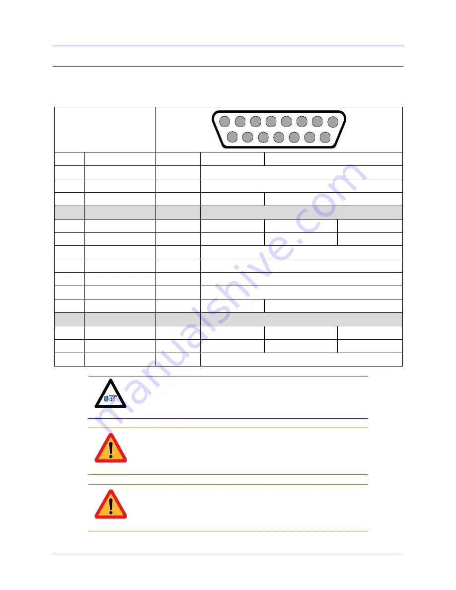
X1-X8: D-sub DA-15F
Mating: D-sub DA-15M
8
7
6
5
4
3
2
1
15
14
13
12
11
10
9
Pin#
Symbol
Function
Primary Use
Alternate Use
1
CHA +
Input
Encoder A +
2
CHB +
Input
Encoder B +
3
CHC +
Input
Index C +
Amp.
4
ENCPWR
Output
Encoder Power 5 VDC (max 250 mA per channel)
5
CHU / DIR +
In / Out
Halls U
Direction Out +
Serial Data–
6
CHW / PUL +
In / Out
Halls W
Pulse Out +
Serial Clock–
7
2.5V
Output
2.5 VDC Reference power
8
PTC
Input
Motor Thermal Input
9
CHA –
Input
Encoder A –
10
CHB –
Input
Encoder B –
11
CHC –
Input
Index C –
Amp. Enable –
12
GND
Common
Common ground
13
CHV / DIR –
In / Out
Halls V
Direction Out –
Serial Clock+
14
CHT / PUL –
In / Out
Halls T
Pulse Out –
Serial Data+
15
Note
Quadrature encoders can be wired in and processed regardless of the
encoder feedback option(s) the Power Brick Controller is ordered
with.
Caution
The +5 VDC encoder power is limited to ~250 mA per channel. For
encoders requiring more current, the +5 VDC power can be alternately
brought in externally through the +5 VDC ENC connector.
Caution
Encoders requiring a voltage level other than +5 VDC (higher or
lower) should be powered up using an external power supply directly
into the encoder.


