SWT4 User Manual v3.1
Installation
21
5. Press the soil surface with your boots gently to the shaft to close
the gap.
6. Push the shaft water protection disk down to cover the soil surface.
This prevents water from running down into the borehole along the
shaft.
7. Leave the protective plastic cover on the plug whenever the plug is
not connected!
8. Connect the signal cables as described in the chapter
Connecting
the SWT4 or SWT4R
on page 23.
9. The Tensiometer will respond to changes in the soil water tension
faster if there is no air inside the system and the soil water
conductivity is high.
10. Write down the serial number, position, installation angle and
depth.
11. Slide the supplied thermal insulation tube over the shaft end and
the refilling tubes. Bend the signal cable and lead it back through
the thermal tube.
12. Protect the cables against rodent bites. Lead the cables through
plastic pipes or use the plastic protection tubes, conduit or
trunking. Contact Delta-T for details.
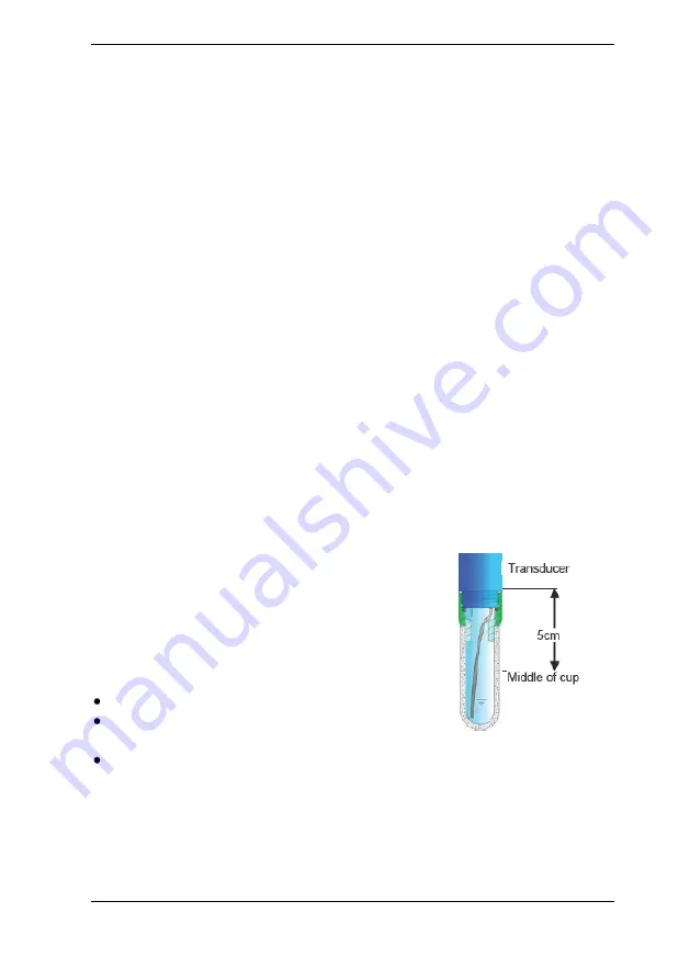
3.4 Offset correction for non horizontal installations
The pressure transducer is calibrated without a
cup. Thus, no compensation is required for
horizontal installations.
If a SWT4 or SWT4R is installed in a non
horizontal position, the vertical water column
draws on the pressure sensor and causes an
offset shift.
Compensate the offset:
by calculation,
by entering the installation angle in the
Infield7 (SWT-MR) for spot readings,
in the configuration of a data logger by setting an offset.
The middle of the cup is regarded to be the measuring level. The
correction is largest for a vertical water column (at 0
o
) and varies as the
cosine of the installation angle, as shown on the table below. In an
absolutely horizontal position the offset is zero.


