C h a p t e r 1 4 D M C N E T
16#012C.
4. The users have to write 3 into bit 11~bit 8 in SR1072 (SR1172, SR1272…).
5. The users can check whether the reading of a value is correct by means of bit 11~bit 8
in SR1073 (SR1173, SR1273…). If an error occurs, an error code will be stored in
(SR1077, SR1076) ((SR1177, SR1176), (SR1277, SR1276)…). If the reading of a value
is successful, the value of bit 11~bit8 in SR1073 (SR1173, SR1273…) will be 0.
6. After a value is read successfully, the users can know the value by means of (SR1077,
SR1076) ((SR1177, SR1176), (SR1277, SR1276)…).
7. The users can write a value into another servo drive or read a value from another servo
drive only after the setting of the servo used is complete, or an error occurs in the servo
used.
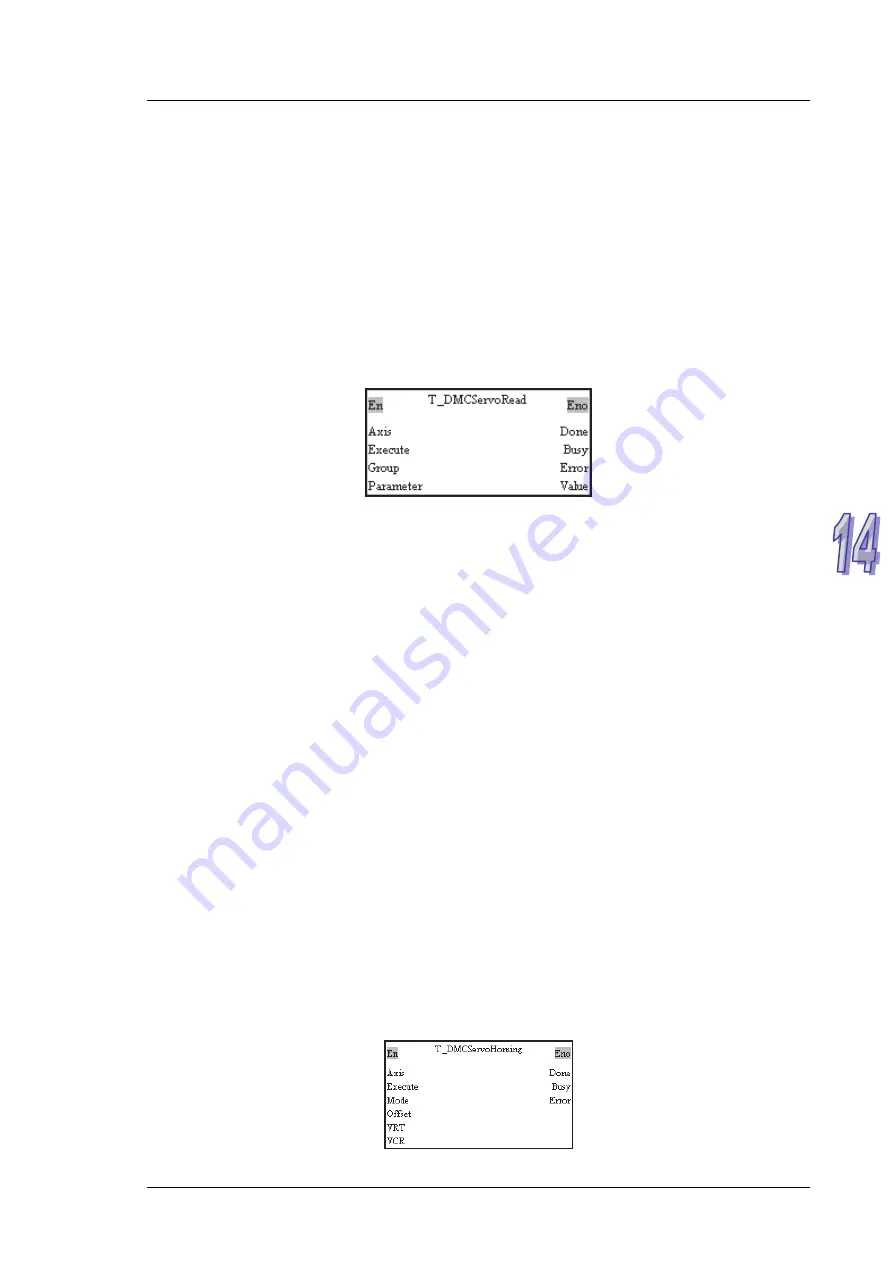
Using a motion control function block
Users can read a value from a servo drive by means of the motion control function block
T_DMCServoRead.
Please refer to chapter 5 for more information about the input pins and the output pins in the
motion control function block T_DMCServoRead.
14.6
DMCNET Motion Control
Retuning
home
Using special data registers
Before users instruct the servo drive used to return home by means of a DMCNET, they
have to make sure of the following points.
1. The value of bit 0~bit 3 in SR1073 (SR1173, SR1273…) is 2, that is, the servo drive
used is ON.
2. When the servo drive used touches the left/right limit switch set and DOG’s signal, it
determines its operation. The users have to connect a left/right limit switch and DOG to
the connector on the servo drive used. The users have to refer to section 3.4.2 in
ASDA-A2 Series User Manual for more information.
After the users make sure of the points above, they can set a mode of returning home.
1. The users have to write 4 into bit 11~bit 8 in SR1072 (SR1172, SR1272…).
2. The users have to set a way in which the servo drive used returns home by means of
SR1078 (SR1178, SR1278…). After SR1078 (SR1178, SR1278…) is set, the servo
drive used will begin to return home.
3. When the servo drive used returns home, the value of bit11~bit 8 in SR1073 (SR1173,
SR1273…) is 1. After the servo drive used returns home, the value of bit 11~bit 8 in
SR1073 (SR1173, SR1273…) will become 0.
4. After the servo drive used returns home, its present position will be the same as the
present position of its corresponding axis.
Using a motion control function block
Users can instruct a servo drive to return home by means of the motion control function
block T_DMCServoHoming.
1 4 - 11
Summary of Contents for AH500
Page 9: ...viii...
Page 53: ...AH500 Motion Control Module Manual Wiring AH10PM 5A and a Yaskawa servo drive 2 32...
Page 55: ...AH500 Motion Control Module Manual Wiring AH10PM 5A and a Fuji servo drive 2 34...
Page 115: ...AH500 Motion Control Module Manual 4 16 MEMO...
Page 375: ...AH500 Motion Control Module Manual 5 260 MEMO...
Page 383: ...AH500 Motion Control Module Manual 6 8 MEMO...
Page 419: ...AH500 Motion Control Module Manual 7 36 MEMO...
Page 436: ...Chapter 8 Electronic Cam 8 17...
Page 483: ...AH500 Motion Control Module Manual 10 8 MEMO...
Page 505: ...AH500 Motion Control Module Manual 12 8 MEMO...
Page 515: ...AH500 Motion Control Module Manual 13 10 MEMO...
Page 544: ...Appendix A Error Code Table Table of Contents A 1 Error Code Table A 2 A 1...


