C h a p t e r 1 4 D M C N E T
Users can check the status of a servo drive by setting P0-02 in the servo drive to 16#120.
After P0-02 in a servo drive is set to 16#120, users can view the value shown on the display
of the servo drive.
Value shown on the
display of a servo drive
Description
16#06
The servo drive is waiting to connect to a DMCNET.
16#80
The servo drive connects to a DMCNET successfully.
16#111
The servo drive is connected to an AH500 series
motion control module.
Starting/Stopping a servo drive
Using special data registers
If the status of a servo drive is that the servo drive is OFF, users can start or stop the
servo drive.
1. If the value of bit 0~bit 3 in SR1072 (SR1172, SR1272…) is 1, the servo drive used
will be stopped. If the value of bit 0~bit 3 in SR1072 (SR1172, SR1272…) is 2, the
servo drive used will be started.
2. After a command is sent to a servo drive, users can check whether the servo drive
is started by means of bit 0~bit 3 in SR1073 (SR1173, SR1273…).
Using a motion control function block
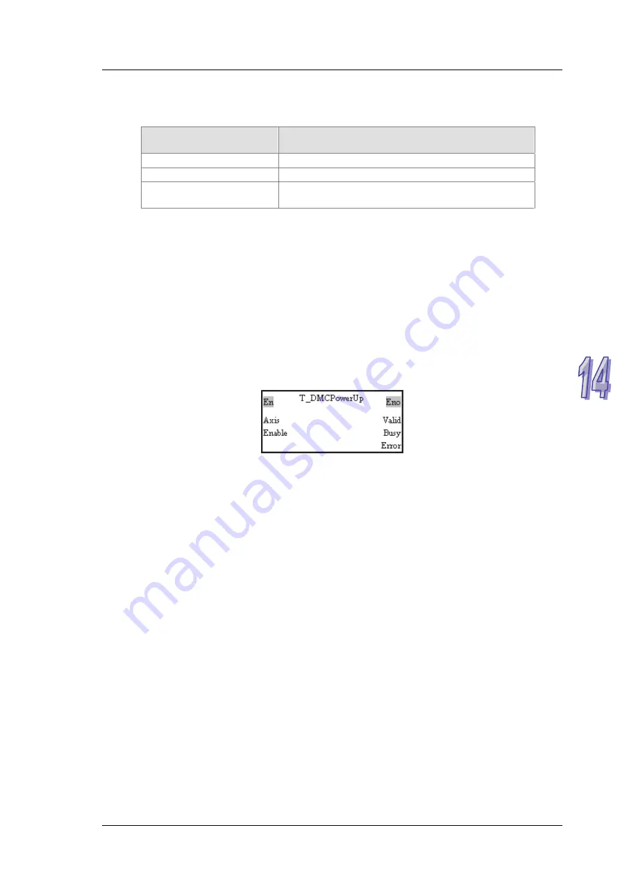
Users can start/stop a servo drive by means of the motion control function block
T_DMCPowerUp.
Please refer to chapter 5 for more information about the input pins and the output pins
in the motion control function block T_DMCPowerUp.
14.5
Reading Data from a Servo Drive/Writing Data
into a Servo Drive
Users can change or read the values of parameters in a servo drive on a DMCNET by means of the
AH500 series motion control module which is connected to the servo drive. They can only set one
servo drive at a time. After one servo drive is set, they can set another servo drive in the same way.
Before the users set a servo drive, they have to check whether the servo drive is connected by
means of bit 0~bit 3 in SR1073 (SR1173, SR1273…). After the users make sure that a servo drive is
connected, they can use other register to write data into the servo drive, and read data from the
servo drive.
Steps of writing a value into a servo drive
Using special data registers
1. Users have to make sure of the node ID of the servo drive used. If the node ID of the
servo drive used is 1, the first axis will be used. If the node ID of the servo drive used is
2, the second axis will be used. If the node ID of the servo drive used is
3/4/5/6/7/8/9/10/11/12, the 3
rd
/4
th
/5
th
/6
th
/7
th
/8
th
/9
th
/10
th
/11
th
/12
th
axis will be used. Only
one axis can be selected at a time.
2. The users have to check whether the status of the servo drive used is that the servo
drive is OFF/ON by means of bit 0~bit 3 in SR1073 (SR1173, SR1273…).
3. After the users refer to the description of a parameter, they can know the group number
assigned to the parameter, the parameter number assigned to the parameter, whether
the parameter is a 16-bit/32-bit parameter, and whether the parameter can be set when
1 4 - 9
Summary of Contents for AH500
Page 9: ...viii...
Page 53: ...AH500 Motion Control Module Manual Wiring AH10PM 5A and a Yaskawa servo drive 2 32...
Page 55: ...AH500 Motion Control Module Manual Wiring AH10PM 5A and a Fuji servo drive 2 34...
Page 115: ...AH500 Motion Control Module Manual 4 16 MEMO...
Page 375: ...AH500 Motion Control Module Manual 5 260 MEMO...
Page 383: ...AH500 Motion Control Module Manual 6 8 MEMO...
Page 419: ...AH500 Motion Control Module Manual 7 36 MEMO...
Page 436: ...Chapter 8 Electronic Cam 8 17...
Page 483: ...AH500 Motion Control Module Manual 10 8 MEMO...
Page 505: ...AH500 Motion Control Module Manual 12 8 MEMO...
Page 515: ...AH500 Motion Control Module Manual 13 10 MEMO...
Page 544: ...Appendix A Error Code Table Table of Contents A 1 Error Code Table A 2 A 1...


