background image

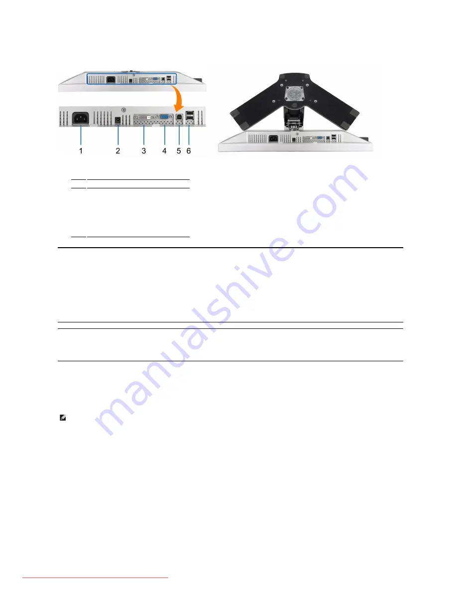
Bottom View  


Bottom view

Bottom view with monitor stand

Label Description

1

AC power cord connector

2

DC power connector for Dell Soundbar

3

DVI connector

4

VGA connector

5

USB upstream port

6

USB downstream ports

Monitor Specifications 

The following sections give you information about the various power management modes and pin assignments for various connectors for your monitor.  

Power Management Modes 

If you have VESA's DPM™ compliance display card or software installed in your PC, the monitor can automatically reduce its power consumption when not in use. This is referred to as 

Mode

*. If the computer detects input from keyboard, mouse, or other input devices, the monitor automatically resumes functioning. The following table shows the power consumption and signaling 

of this automatic power saving feature:  

The OSD will only function in the 

normal operation

 mode. When the 

menu

 or 

plus

 buttons are pressed in Active-off mode, one of the following messages will be displayed:

Analog Input In Power Save Mode. Press Computer Power Button or Any Key on Keyboard or Move Mouse 

OR 


Digital Input In Power Save Mode. Press Computer Power Button or Any Key on Keyboard or Move Mouse


Activate the computer and the monitor to gain access to the OSD. 

* Zero power consumption in OFF mode can only be achieved by disconnecting the main cable from the monitor. 

VESA Modes

Horizontal Sync

Vertical Sync 

Video

Power Indicator

Power Consumption

Normal operation (with Dell Soundbar and USB active)

Active

Active

Active 

Green

70 W (maximum)

Normal operation

Active

Active

Active 

Green

42 W (typical)

Active-off mode

Inactive

Inactive

Blanked

Amber

Less than 2 W

Switch off

-

-

-

Off

Less than 1 W

NOTE:

 This monitor is 

ENERGY STAR

®

-compliant as well as TCO '99/TCO '03 power management compatible.

Downloaded from ManualMonitor.com Manuals

Summary of Contents for UltraSharp 2009W

Page 1: ...08 Rev A00 About Your Monitor Product Features Identifying Parts and Controls Monitor Specifications Universal Serial Bus USB Interface Plug and Play Capability Maintenance Guidelines Setting Up the Monitor Attaching the Stand Connecting the Monitor Organizing the Cables Attaching the Soundbar Optional Removing the Stand Operating the Monitor Using the Front Panel Controls Using the On Screen Disp...

Page 2: ...estal and VESA 100 mm mounting holes for flexible mounting solutions Plug and play capability if supported by your system On Screen Display OSD adjustments for ease of set up and screen optimization Software and documentation CD includes an information file INF Image color Matching File ICM and product documentation Energy Saver feature for Energy Star compliance Security lock slot Identifying Par...

Page 3: ... 3 Security lock slot Use a security lock with the slot to help secure your monitor 4 Dell Soundbar mounting brackets Attach the optional Dell Soundbar 5 Regulatory rating label Lists the regulatory approvals 6 Stand removal button Press to release the stand 7 Cable management slot Help organize cables by placing them through the slot 8 Lock down release button Push the monitor down press the butt...

Page 4: ...ture The OSD will only function in the normal operation mode When the menu or plus buttons are pressed in Active off mode one of the following messages will be displayed Analog Input In Power Save Mode Press Computer Power Button or Any Key on Keyboard or Move Mouse OR Digital Input In Power Save Mode Press Computer Power Button or Any Key on Keyboard or Move Mouse Activate the computer and the mo...

Page 5: ...3 Video Blue 4 GND 5 Self test 6 GND R 7 GND G 8 GND B 9 Computer 5V 3 3V 10 GND sync 11 GND 12 DDC data 13 H sync 14 V sync 15 DDC clock Pin Number 24 pin Side of the Connected Signal Cable 1 TMDS RX2 2 TMDS RX2 3 TMDS Ground 4 Floating 5 Floating 6 DDC Clock 7 DDC Data 8 Floating Downloaded from ManualMonitor com Manuals ...

Page 6: ...DS Ground 12 Floating 13 Floating 14 5V 3 3V power 15 Self test 16 Hot Plug Detect 17 TMDS RX0 18 TMDS RX0 19 TMDS Ground 20 Floating 21 Floating 22 TMDS Ground 23 TMDS Clock 24 TMDS Clock Downloaded from ManualMonitor com Manuals ...

Page 7: ...ption High speed 480 Mbps 2 5W Max each port Full speed 12 Mbps 2 5W Max each port Low speed 1 5 Mbps 2 5W Max each port Pin Number 4 pin Side of the connector 1 DMU 2 VCC 3 DPU 4 GND Pin Number 4 Pin Side of the Signal Cable 1 VCC 2 DMD 3 DPD 4 GND NOTE USB 2 0 functionality requires a USB 2 0 capable computer NOTE The monitor s USB interface works only when the monitor is on or in power save mod...

Page 8: ...erating the Monitor Flat Panel Specifications 2009W color gamut typical is based on CIE1976 102 and CIE1931 92 test standards Screen type Active matrix TFT LCD Screen dimensions 20 inches 20 inch viewable image size Preset display area Horizontal 433 44 mm 17 06 inches Vertical 270 90 mm 10 67 inches Pixel pitch 0 258 mm Viewing angle 160 vertical typ 170 horizontal typ Luminance output 300 cd m t...

Page 9: ...Downloaded from ManualMonitor com Manuals ...

Page 10: ...try and product and some services may not be available in your area To contact Dell for sales technical support or customer service issues Back to Contents Page CAUTION Use of controls adjustments or procedures other than those specified in this documentation may result in exposure to shock electrical hazards and or mechanical hazards NOTE If you do not have an active Internet connection you can f...

Page 11: ... between two different video signals that may be connected to your monitor l VGA input l DVI D input If both VGA and DVI cables are connected to one PC this monitor displays an image automatically as long as a video signal is present in either VGA or DVI outputs On a display connected to two PCs set equal time for both screen savers The video input from the movement of the first mouse will activat...

Page 12: ...on to turn the monitor on and off The green LED indicates the monitor is on and fully functional An amber LED indicates DPMS power save mode NOTE If you change the settings and then either proceed to another menu or exit the OSD menu the monitor automatically saves those changes The changes are also saved if you change the settings and then wait for the OSD menu to disappear 1 Push the MENU button...

Page 13: ...cognizes your monitor on startup the Auto Adjustment function optimizes the display settings for use with your particular setup NOTE In most cases Auto Adjust produces the best image for your configuration NOTE AUTO ADJUST option is only available when you are using the analog VGA connector INPUT SOURCE Use the INPUT SOURCE menu to select between different video signals that may be connected to yo...

Page 14: ...diting multimedia movies etc Cool Mode Cool Mode is selected to obtain a bluish tint This color setting is typically used for text based applications spreadsheets programming text editors etc Custom R G B Mode Use the or button to increase or decrease each of the three colors R G B independently in single digit increments from 0 to 100 Presets Mode Video You can choose different color presets for ...

Page 15: ...Exit Menu Push to exit the OSD main menu DISPLAY SETTINGS Display Setting submenu Display Setting submenu for VGA input Display Setting submenu for DVI D input Downloaded from ManualMonitor com Manuals ...

Page 16: ...Downloaded from ManualMonitor com Manuals ...

Page 17: ...Downloaded from ManualMonitor com Manuals ...

Page 18: ...Downloaded from ManualMonitor com Manuals ...

Page 19: ...Downloaded from ManualMonitor com Manuals ...

Page 20: ...Downloaded from ManualMonitor com Manuals ...

Page 21: ...r To connect your monitor to the computer perform the following steps instructions l Turn off your computer and disconnect the power cable l Connect either the white digital DVI D or the blue analog VGA display connector cable to the corresponding video port on the back of your computer Do not use both cables on the same computer Use both the cables only when they are connected to two different co...

Page 22: ...or into a nearby outlet l Turn on the monitor and the computer If your monitor displays an image installation is complete If it does not display an image see Solving Problems l Use the cable holder on the monitor stand to organize the cables Organizing the Cables After attaching all the necessary cables to your monitor and computer See Connecting Your Monitor for cable attachment use the cable man...

Page 23: ...ptional Dell Soundbar only 1 Working from the rear of the monitor attach the Dell Soundbar by aligning the two slots with the two tabs along the bottom rear of the monitor 2 Slide the Dell Soundbar to the left until it snaps into place 3 Connect the Dell Soundbar with the DC power connector 4 Insert the mini stereo plug from the rear of the Dell Soundbar into the computer s audio output jack NOTE ...

Page 24: ... CAUTION Before you begin any of the procedures in this section follow the Safety Instructions The floating dialog box should appear on screen against a black background if the monitor cannot sense a video signal and is working correctly While in self test mode the power LED remains green Also depending upon the selected input one of the dialogs shown below will continuously scroll through the scr...

Page 25: ...appears in self test mode l Check for bent or broken pins in the video cable connector l Restart the computer in the safe mode Safety Related Issues Visible signs of smoke or sparks l Do not perform any troubleshooting steps l Contact Dell immediately Intermittent Problems Monitor malfunctions on off l Ensure that the video cable connecting the monitor to the computer is connected properly and is ...

Page 26: ...Downloaded from ManualMonitor com Manuals ...

Reviews: