background image

Expansion card

Removing the expansion card

1. Follow the procedure in 

Before working inside your computer

.

2. Remove the 

side cover

.

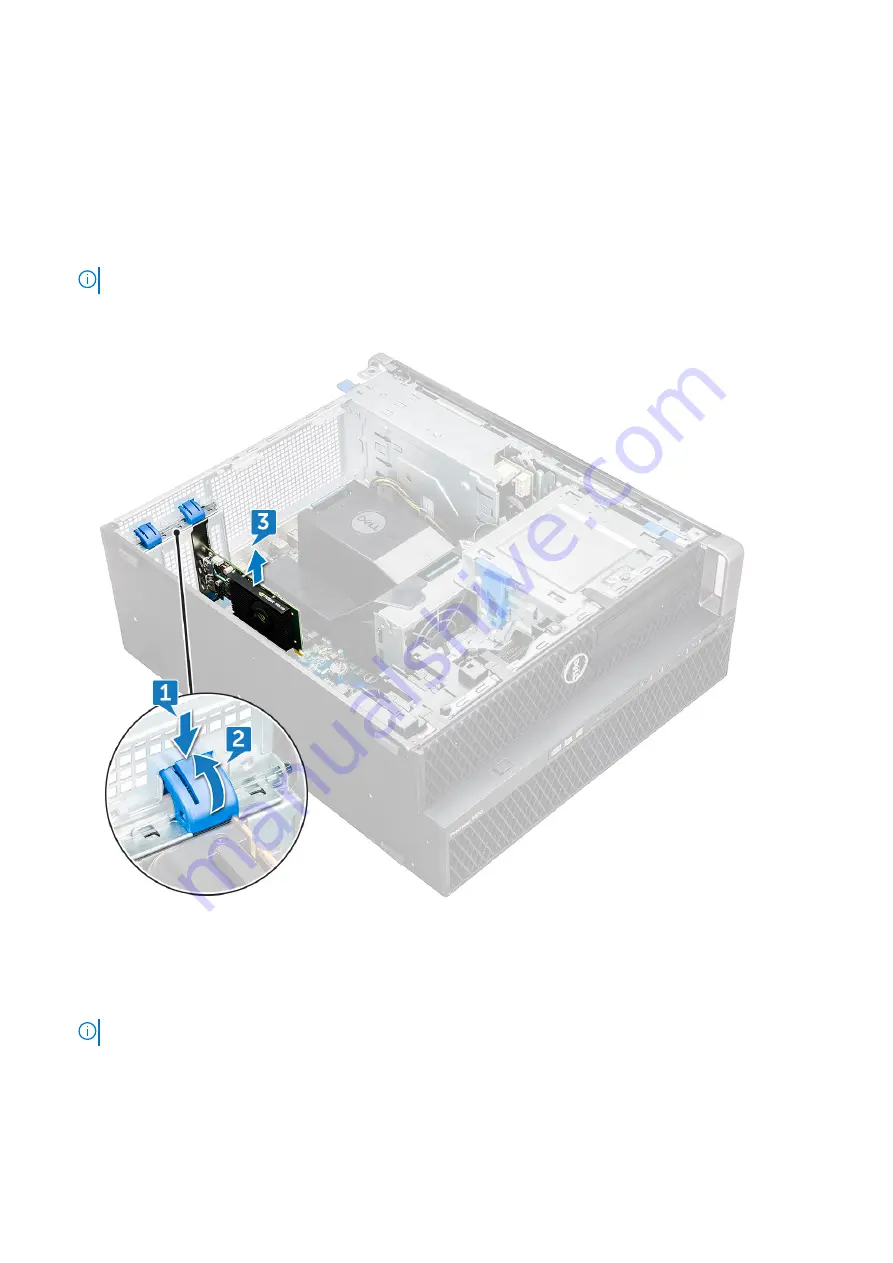
3. To remove the expansion card:

NOTE:

 For expansion card with VGA power, disconnect the data or power cable connected to the expansion card.

a. Press [1] and rotate the expansion card locking latch backward [2], to unlock the filler bracket.
b. Lift the expansion card [3] from the PCIe slot on the system board.

Installing the expansion card

1. Align and place the expansion card to the PCIe slot on the system board.
2. Press it down so that it is securely seated on the slot.

NOTE:

 For expansion card with VGA power, connect the data or power cable to the expansion card.

3. Rotate both the expansion card locking latch forward, on the filler bracket, to secure the expansion card to the system

board.

4. Install the 

side cover

.

5. Follow the procedure in 

After working inside your computer

.

54

Removing and installing components

Summary of Contents for Precision 5820 Tower

Page 1: ...Dell Precision 5820 Tower Owner s Manual Regulatory Model D02T Regulatory Type D02T002 August 2021 Rev A06 ...

Page 2: ...tial damage to hardware or loss of data and tells you how to avoid the problem WARNING A WARNING indicates a potential for property damage personal injury or death 2017 2021 Dell Inc or its subsidiaries All rights reserved Dell EMC and other trademarks are trademarks of Dell Inc or its subsidiaries Other trademarks may be trademarks of their respective owners ...

Page 3: ...he side cover 18 Installing the side cover 20 Power supply unit PSU 20 Removing the PSU 20 Installing the PSU 21 Front bezel 21 Removing the front bezel 21 Installing the front bezel 23 Hard Disk Drive bezel 23 Removing HDD bezel 23 Installing HDD bezel 24 Hard disk drive assembly 24 Removing the HDD carrier 24 Installing the HDD carrier 26 Removing the HDD 26 Installing the HDD 28 NVMe Flexbay 28...

Page 4: ...ing the air shroud 52 Memory 52 Removing the memory module 52 Installing the memory module 52 PCIe NVMe card 53 Removing the PCIe NVMe card 53 Installing the PCIe NVMe card 53 Expansion card 54 Removing the expansion card 54 Installing the expansion card 54 Coin cell battery 55 Removing the coin cell battery 55 Installing the coin cell battery 55 System fan 56 Removing the System fan 56 Installing...

Page 5: ...79 Chapter 4 Technology and components 80 Memory configuration 80 Technologies list 80 MegaRAID 9440 8i and 9460 16i controller 82 Teradici PCoIP 84 Chapter 5 System specifications 88 System specifications 88 Memory specifications 88 Video specifications 89 Audio specifications 90 Network specifications 90 Card slots 90 Storage specifications 90 External connectors 91 Power specifications 91 Physi...

Page 6: ...password 107 Deleting or changing an existing system setup password 107 Chapter 7 Software 108 Operating system 108 Downloading drivers 108 Chipset drivers 109 Graphics controller driver 109 Ports 109 USB drivers 110 Network driver 110 Audio drivers 110 Storage controller drivers 110 Other drivers 111 Chapter 8 Troubleshooting 112 Dell Enhanced Pre Boot System Assessment ePSA Diagnostic 3 0 112 Ru...

Page 7: ... hot key combinations Topics Front view Back view Internal view Major components of your system Front view 1 5 25 inch ODD bracket 2 Slim optical disk drive 3 Headset port 4 USB 3 1 Gen 1 Type C 5 USB 3 1 Gen 1 Type C port with PowerShare 6 USB 3 1 Gen 1 ports 7 SD card slot 8 HDD activity LED 9 Power button 1 Chassis 7 ...

Page 8: ...ower cable connector 3 Microphone Line in port 4 Line out port 5 Serial port 6 PS 2 Mouse port 7 PS 2 Keyboard port 8 Network port 9 USB 3 1 Gen1 ports 10 USB 3 1 Gen1 port supports smart Power On 11 PCIe expansion slot 8 Chassis ...

Page 9: ...Internal view 1 PSU bracket 2 HDD bezel lock unlock button 3 ODD 5 25 bracket 4 Intrusion switch 5 PCIe holder 6 Coin cell battery 7 Powered GPU 8 Air shroud Chassis 9 ...

Page 10: ...1 Heat sink 2 PSU distribution board 3 HDD fan 4 Flex bay 5 Speaker 6 Drive access release latch 7 System board 10 Chassis ...

Page 11: ... switch 5 5 25 inch ODD bracket 6 5 25 inch Optical Disk Drive 7 System fan 8 Power Distribution Board 9 Slim Optical Disk Drive 10 NVMe Flexbay 11 Front input and output panel 12 Front input and output bezel 13 Hard Disk Drive bezel 14 Front bezel 15 Computer chassis 16 System board 17 Expansion card 18 Memory 19 Processor 20 Heat sink and CPU fan assembly 21 System fan Chassis 11 ...

Page 12: ... provides a list of components and their part numbers for the original system configuration purchased These parts are available according to warranty coverages purchased by the customer Contact your Dell sales representative for purchase options 12 Chassis ...

Page 13: ...uthorized by Dell is not covered by your warranty See the safety instructions that is shipped with the product or at www dell com regulatory_compliance CAUTION Before touching anything inside your computer ground yourself by touching an unpainted metal surface such as the metal at the back of the computer While you work periodically touch an unpainted metal surface to dissipate static electricity ...

Page 14: ... field service kit The components of an ESD field service kit are Anti Static Mat The anti static mat is dissipative and parts can be placed on it during service procedures When using an anti static mat your wrist strap should be snug and the bonding wire should be connected to the mat and to any bare metal on the system being worked on Once deployed properly service parts can be removed from the ...

Page 15: ... reverse order NOTE Disconnect all power sources before opening the computer cover or panels After you finish working inside the computer replace all covers panels and screws before connecting to the power source WARNING Before working inside your computer read the safety information that shipped with your computer For additional safety best practices information see the Regulatory Compliance Home...

Page 16: ...cable from the network device 5 Disconnect your computer and all attached devices from their electrical outlets 6 Press and hold the power button while the computer is unplugged to ground the system board NOTE To avoid electrostatic discharge ground yourself by using a wrist grounding strap or by periodically touching an unpainted metal surface at the same time as touching a connector on the back ...

Page 17: ...ernal chassis speaker Air shroud Memory PCIe NVMe card Expansion card Coin cell battery System fan Fan bracket PCIe holder Heat sink and CPU fan assembly Processor Front system fan VROC module System board RAID controller battery RAID controller battery bracket Screw size list Table 1 Screw list Component Screw type Quantity Slim ODD Bracket 6 32 UNC X6 0mm 1 FIO Cable Clip 6 32X1 4 inches 1 FIO B...

Page 18: ...ket M3X4 5mm 4 2 5 HDD Bracket M3X4 5mm 4 2nd CPU Support Bracket 6 32X1 4 inches 2 2nd CPU Board 6 32X1 4 inches 5 UPI Fixed Bracket M3X5 0mm 1 CPU Cooler T 30 torx bolt 4 Liquid Cooler Module 6 32X1 4 inches 6 32 UNC X3 5mm T 30 torx bolt 4 6 4 M 2 Carrier Cover M2X6mm M2X3mm 1 2 Recommended tools The procedures in this document require the following tools Phillips 0 screwdriver Phillips 1 screw...

Page 19: ... side cover is off Also the system will shut down if the side cover is removed while the system is on 2 To remove the side cover 3 Press the latch 4 Pull the latch 1 upward and rotate it to release the cover 2 Removing and installing components 19 ...

Page 20: ...ess the system cover until it clicks into place CAUTION The system will not power on without the side cover Also the system will shut down if the side cover is removed while the system is on 4 Follow the procedure in After working inside your computer Power supply unit PSU Removing the PSU 1 Follow the procedure in Before working inside your computer 2 Disconnect the power cable from the system 20...

Page 21: ...ect the power cable to the system 3 Follow the procedure in After working inside your computer Front bezel Removing the front bezel 1 Follow the procedure in Before working inside your computer 2 Remove the side cover 3 To remove the front bezel a Press the latch and pry the retention tabs to release the front bezel from the system Removing and installing components 21 ...

Page 22: ...b Rotate the bezel forward and lift the front bezel away from the system 22 Removing and installing components ...

Page 23: ...ocedure in After working inside your computer Hard Disk Drive bezel Removing HDD bezel 1 Follow the procedure in Before working inside your computer 2 Remove the side cover 3 To remove the HDD bezel a Press the blue unlock button 1 on the edge of ODD bay b Slide the latch 2 to the unlock position on the front I O bezel c Rotate forward and lift the HDD bezel 3 away from the system Removing and ins...

Page 24: ...all the side cover 4 Follow the procedure in After working inside your computer Hard disk drive assembly Removing the HDD carrier 1 Follow the procedure in Before working inside your computer 2 Remove the a side cover NOTE Do not remove the side cover if the front I O bezel is unlocked b HDD bezel 3 To remove the HDD carrier a Press the release button 1 to unlock the latch 2 24 Removing and instal...

Page 25: ...b Pull the latch to slide the carrier out of the HDD slot Removing and installing components 25 ...

Page 26: ...installing the carrier 2 Lock the latch 3 Install the following components a HDD bezel b side cover 4 Follow the procedure in After working inside your computer Removing the HDD 1 Follow the procedure in Before working inside your computer 2 Remove the following a side cover b HDD bezel c HDD carrier 26 Removing and installing components ...

Page 27: ...nch HDD a Expand one side of the carrier b Lift the hard drive out of the carrier 4 To remove the 2 5 inch HDD a Expand two sides of the carrier b Lift the hard drive out of the carrier Removing and installing components 27 ...

Page 28: ... HDD carrier b HDD bezel c side cover 4 Follow the procedure in After working inside your computer NVMe Flexbay Removing the NVMe Flexbay 1 Follow the procedure in Before working inside your computer 2 Remove the a side cover NOTE Do not remove the side cover if the front I O bezel is unlocked b HDD bezel 3 To remove the NVMe flexbay a Press the release button 1 to unlock the latch 2 28 Removing a...

Page 29: ...b Pull the latch to slide the carrier out of the HDD slot Removing and installing components 29 ...

Page 30: ...ove the SSD carrier from the NVMe flexbay a Press the release button to slide the M 2 SSD carrier out of the NVMe flexbay b Pull the M 2 SSD carrier out of the NVMe flexbay 30 Removing and installing components ...

Page 31: ...5 To remove the SSD from the SSD carrier a Remove the screws on either side of the SSD b Remove the screw from the top of the SSD carrier Removing and installing components 31 ...

Page 32: ...c Slide the SSD cover from the top of the carrier d Slide the SSD out of the M 2 slot on the carrier 32 Removing and installing components ...

Page 33: ...Installing the NVMe flexbay 1 To install the SSD in the carrier a Remove the dummy SSD blank from the SSD carrier b Peel off the tape from the SSD carrier Removing and installing components 33 ...

Page 34: ...c Peel off the adhesive tape from the SSD carrier cover 2 Install the SSD in the carrier 34 Removing and installing components ...

Page 35: ...efore installing the carrier 6 Lock the latch 7 Install the following components a HDD bezel b side cover 8 Follow the procedure in After working inside your computer Slim Optical Disk Drive Removing the slim ODD 1 Follow the procedure in Before working inside the computer 2 Remove the side cover 3 To remove the slim ODD a Remove the screw 1 that secures the slim ODD and push the slim ODD 2 out of...

Page 36: ...b Slide the slim ODD out of the system 36 Removing and installing components ...

Page 37: ...n After working inside your computer Front input and output bezel Removing front input and output bezel 1 Follow the procedure in Before working inside your computer 2 Remove the a side cover b front bezel 3 To remove the front input and output I O bezel a Pry the four retention tabs 1 from the chassis and push the bezel out from the chassis 2 Removing and installing components 37 ...

Page 38: ...b Lift the bezel from the chassis 38 Removing and installing components ...

Page 39: ...m to the chassis 3 Install the a front bezel b side cover 4 Follow the procedure in After working inside your computer Optical Disk Drive Removing the ODD 1 Follow the procedure in Before working inside your computer 2 Remove the a side cover b front bezel 3 To remove the ODD a Remove the optical drive data cable and optical drive power cable from the ODD Removing and installing components 39 ...

Page 40: ...b Push the optical drive release button 1 and push the optical drive out of the system c Slide the ODD 2 from the ODD bracket 40 Removing and installing components ...

Page 41: ...nstall the a front bezel b side cover 5 Follow the procedure in After working inside your computer 5 25 inch ODD bracket Removing the 5 25 ODD bracket 1 Follow the procedure in Before working inside your computer 2 Remove the a side cover b front bezel c ODD 3 To remove the ODD bracket a Remove the five screws 1 2 that secure the bracket to the chassis Removing and installing components 41 ...

Page 42: ...b Slide the ODD bracket toward the rear of the system and lift it away from the chassis 42 Removing and installing components ...

Page 43: ... and output panel Removing front input and output panel 1 Follow the procedure in Before working inside your computer 2 Remove the a side cover b front bezel c front input and output bezel d 5 25 inch ODD bracket 3 To remove the front input and output I O panel a Disconnect the intrusion switch cable 1 USB 3 1 cable 2 front I O power cable 3 USB 3 1 cable 4 Speaker cable 5 Audio cable 6 Removing a...

Page 44: ...disconnect the cable by pulling the connector end Pulling the cable wires may loosen them from the connector b Remove the screw 1 that secures the front I O panel to the chassis and slide the I O panel out of the chassis 2 44 Removing and installing components ...

Page 45: ...ssis hole 3 Tighten the screw to secure the front I O panel to the chassis 4 Connect the following cables intrusion switch cable USB 3 1 cable front I O power cable front I O power cable USB 3 1 cable speaker cable audio cable 5 Install the a front input and output bezel b 5 25 inch ODD bracket c front bezel d side cover Removing and installing components 45 ...

Page 46: ...llow the procedure in Before working inside your computer 2 Remove the a side cover b front bezel c front input and output bezel d 5 25 inch ODD bracket e front input and output panel 3 To remove the input and output I O panel bracket a Remove the two screws b Slide the I O module out of the bracket 46 Removing and installing components ...

Page 47: ...er working inside your computer Intrusion switch Removing the Intrusion switch 1 Follow the procedure in Before working inside your computer 2 Remove the a side cover b front bezel c 5 25 inch ODD bracket 3 To remove the intrusion switch a Disconnect the intrusion cable 1 from the I O module b Remove the screw 2 that secures the intrusion switch to the chassis c Lift the intrusion switch and remov...

Page 48: ...hassis 3 Connect the cable to the system board 4 Install the a 5 25 inch ODD bracket b front bezel c side cover 5 Follow the procedure in After working inside your computer Internal chassis speaker Removing the internal chassis speaker 1 Follow the procedure in Before working inside your computer 2 Remove the 48 Removing and installing components ...

Page 49: ...with its cable out of the system Installing the internal chassis speaker 1 Press and hold the tabs on either side of the intrusion speaker and slide the speaker module into the slot to secure it to the system 2 Connect the internal chassis speaker cable to the connector on the system chassis 3 Install the a 5 25 inch ODD bracket b front bezel c side cover 4 Follow the procedure in After working in...

Page 50: ...cedure in Before working inside your computer 2 Remove the side cover 3 To remove the air shroud a Press in the securing tabs by holding the air shroud from both the ends and then lift the air shroud from the system 50 Removing and installing components ...

Page 51: ...Removing and installing components 51 ...

Page 52: ... module retention tabs on each side of the memory module 4 Lift the memory module out of the memory slot on the system board WARNING Rotating the memory module out of the slot will cause damage to the memory module Ensure to pull it straight out of the memory module slot Installing the memory module 1 Align the notch on the memory module with the tab on the memory module connector 2 Insert the mem...

Page 53: ...CIe NVMe card from the PCIe slot on the system board 2 Installing the PCIe NVMe card 1 Align and place the PCIe NVMe card to the PCIe slot on the system board 2 Press it down so that it is securely seated on the slot 3 Rotate both the locking latch forward on the filler bracket to secure the expansion card to the system board 4 Install the side cover 5 Follow the procedure in After working inside ...

Page 54: ...t the expansion card 3 from the PCIe slot on the system board Installing the expansion card 1 Align and place the expansion card to the PCIe slot on the system board 2 Press it down so that it is securely seated on the slot NOTE For expansion card with VGA power connect the data or power cable to the expansion card 3 Rotate both the expansion card locking latch forward on the filler bracket to sec...

Page 55: ... battery to allow the battery to pop up from the socket 2 b Lift the coin cell battery out of the system board Installing the coin cell battery 1 Place the coin cell battery into its slot on the system board 2 Press the coin cell battery with positive side facing up until the release latch springs back into place and secures it to the system board 3 To install a side cover Removing and installing ...

Page 56: ...h ODD bracket 3 To remove the system fan a Press the connector tab and disconnect the two fan cables from the system board NOTE Do not pull the connector by the cable wires Instead disconnect the cable by pulling on the connector end Pulling on the cable wires may loosen them from the connector b Remove the screws 1 securing the system fan to the system board and lift the system fan up 2 56 Removi...

Page 57: ...ODD c front bezel d air shroud e side cover 4 Follow the procedure in After working inside your computer Fan bracket Removing the fan from the fan bracket 1 Follow the procedure in Before working inside your computer 2 Remove the a side cover b system fan 3 To remove the fan from the fan bracket a Slide out the four rubber grommets for each fan from the fan chassis 1 Removing and installing compon...

Page 58: ...the fan into the fan bracket 1 Place the fan into the fan bracket 2 Tighten the grommets that secure the fan to the fan bracket 3 Install the a system fan b side cover 4 Follow the procedure in After working inside your computer 58 Removing and installing components ...

Page 59: ...xpansion card 3 To remove the PCIe holder a Press the PCIe holder securing clip 1 and slide the holder 2 out of the chassis Installing the PCIe holder 1 Align and place the PCIe holder to the system chassis 2 Press the holder back until it clicks to the system 3 Install the a side cover Removing and installing components 59 ...

Page 60: ...ur computer 2 Remove the a side cover b air shroud 3 To remove the heat sink and CPU fan assembly a Disconnect the CPU fan cable 1 from the system board b Loosen the four heat sink captive screws 2 in the diagonal order 4 3 2 1 c Gently lift the heat sink and CPU fan assembly 3 from the system NOTE Lay the assembly with the thermal grease facing up 60 Removing and installing components ...

Page 61: ... cable to the system board 4 Install the a air shroud b side cover 5 Follow the procedure in After working inside your computer Removing the CPU fan 1 Follow the procedure in Before working inside your computer 2 Remove the a side cover b air shroud c heat sink and CPU fan assembly 3 To remove the CPU fan a Unroute the CPU fan cable from the cable holder in the bracket b Lay the assembly with the ...

Page 62: ...e Detach the 4 rubber grommets 1 from the CPU fan bracket and lift the fan 2 away from the bracket 62 Removing and installing components ...

Page 63: ... Removing the processor 1 Follow the procedure in Before working inside your computer 2 Remove the a side cover b air shroud c heat sink and CPU fan assembly 3 To remove the processor a Press the left side release lever 1 down then move it inward to release it from the retention hook b Press the right side release lever 2 down then move it inward to release it from the retention hook c Open the re...

Page 64: ...fter working inside your computer Front system fan Removing the front system fan 1 Follow the procedure in Before working inside your computer 2 Remove the a side cover b front bezel c PCIe holder 3 To remove the front system fan a Unroute the following cables from the card holder 3 SATA 0 1 2 3 4 5 cable and ODD 0 1 cable 1 USB 3 1 cable 2 NOTE Do not pull the connector by the cable wires Instead...

Page 65: ...2 that secure the rear system fan to the chassis d Lift the fan to release it from the retention slot in the system chassis 3 Installing the front system fan 1 Align the front system fan to its retention slot in the system chassis Removing and installing components 65 ...

Page 66: ...the system board SATA and ODD cables USB 3 1 cable 5 Install the a PCIe holder b front bezel c side cover 6 Follow the procedure in After working inside your computer VROC module Removing the VROC module Plug out the VROC module from the system board in the upward direction Installing the VROC module Plug in the VROC module to the system board 66 Removing and installing components ...

Page 67: ... memory module e heat sink and CPU fan assembly f front bezel g ODD h 5 25 ODD bracket i system fan j PCIe card holder 3 To remove the system board a To remove the system fan fixed bracket remove the screw 1 that secure the fixed bracket to the system board b Lift the system fan fixed bracket from the system board 2 Removing and installing components 67 ...

Page 68: ... O panel 6 d Disconnect the following cables SATA cables and ODD cables 1 USB 3 1 cable 2 Front system fan cable Flex0 and Flex1 hard drive data cable NOTE Do not pull the connector by the cable wires Instead disconnect the cable by pulling on the connector end Pulling on the cable wires may loosen them from the connector 68 Removing and installing components ...

Page 69: ...e Remove the screws that secure the system board to the chassis Removing and installing components 69 ...

Page 70: ...f Slide the system board towards HDD bracket module to detach it from the system 70 Removing and installing components ...

Page 71: ...g Lift the system board up to remove it from the chassis Removing and installing components 71 ...

Page 72: ...ket and replace the single screw on the system board 5 Connect the following cables audio cable power cable power control cable 24Pin power cable front I O panel SATA cables ODD cables USB 3 1 cables Front system fan cable Flex0 and Flex1 hard drive data cable 6 Install the a PCIe holder b expansion card c memory module d heat sink and CPU fan assembly e system fan f air shroud 72 Removing and ins...

Page 73: ... 2 Slot 5 PCIe x16 wired as x4 3 Slot 4 PCIe x16 4 Slot 3 PCIe x16 wired as x1 5 Slot 2 PCIe x16 6 Slot 1 PCIe x16 wired as x8 7 Memory slots 8 CPU0 9 Memory slots 10 Front panel audio port 11 Power CPU port 12 System fan port 13 Power control port 14 PCIE0 15 PCIE1 16 CPU fan port 17 System fan port 18 Coin cell battery 19 FLEX0 thermal sensor 20 FLEX1 thermal sensor Removing and installing compo...

Page 74: ...esent supported on motherboards designed for Xeon W Series Processors RAID controller battery Removing the RAID controller battery 1 Follow the procedure in Before working inside your computer 2 Remove the side cover 3 To remove the RAID controller battery a Disconnect the RAID controller battery cable from the RAID controller card b Push the securing tab out to release the RAID controller battery...

Page 75: ...c Lift and remove the RAID controller battery Removing and installing components 75 ...

Page 76: ...76 Removing and installing components ...

Page 77: ...onnect the RAID controller battery cable RAID controller battery bracket Removing the RAID controller battery bracket 1 Follow the procedure in Before working inside your computer 2 Remove the side cover 3 Remove the RAID controller battery 4 To remove the RAID controller battery bracket a Lift up the securing tab 1 and slide the RAID controller battery bracket out 2 Removing and installing compon...

Page 78: ...78 Removing and installing components ...

Page 79: ... controller battery bracket 1 Slide and place the RAID controller battery bracket the opposite way it was removed 2 Ensure the tabs on the bracket fits into the holders on the chassis Removing and installing components 79 ...

Page 80: ... only supported on systems using Xeon W Series CPUs Technologies list This section provides information about the technologies that comes with the Dell Precision 5820 Tower The following table lists the basic of technologies that are available on the Dell Precision 5820 Tower systems for Dell internal users only Table 2 Intel Xeon W Series CPUs No Category Technology Browser Path 1 Chipset Intel C...

Page 81: ... Support HOST PCIe x1 PCoIP Dual Host Card TERA Gen 2 CLIENT Dell or other Branded Zero Client TERA Gen 2 Dell Wyse P45 QUAD Monitor Support HOST PCIe x1 PCoIP Quad Host Card TERA Gen 2 Support Dual Terra Card configurations NOTE For further information about the Teradici PCoIP Card host driver installation see Teradici PCoIP Table 3 Intel Core X Series CPUs No Category Technology Browser Path 1 C...

Page 82: ...TA interfaces Based on the dual core SAS3516 or SAS3508 RAID on Chip ROC and 72 bit DDR4 2133 SDRAM these controllers provide bandwidth and IOPS performance increases and are ideal for high end servers utilizing internal storage or connecting to large scale external storage enclosures NOTE The MegaRAID 9440 and 9460 controllers are only supported when using Intel Xeon W Series CPUs Tri Mode SerDes...

Page 83: ... connectivity CacheVault flash back up at power fail Supports bad block management Balance protection and performance for critical applications with RAID levels 0 1 5 6 10 50 and 60 Table 4 Features of MegaRAID 9440 8i and 9460 16i controller 9440 8i 9460 16i Ports 8 internal 16 internal Connectors 2 x SFF8643 4 x SFF8643 x4 Storage Interface Support SATA Eight x1 SAS One x8 Two x4 Four x2 Eight x...

Page 84: ...2013 24 25 Europe EN55022 EN55024 Safety EN IEC UL 60950 RoHS WEEE USA FCC 47 CFR part 15 Subpart B class B Canada ICES 003 Class B Taiwan CNS 13438 Japan VCCI V 3 Australia New Zealand AS NZS CISPR 22 Korea RRA no 2013 24 25 Europe EN55022 EN55024 Safety EN IEC UL 60950 RoHS WEEE OS Support Microsoft Windows VMware vSphere ESXi Red Hat Linux SuSe Linux Ubuntu Linux Oracle Linux CentOS Linux Debia...

Page 85: ... installation location is correct and click Next 9 Click Install NOTE For Windows 7 when the driver is installed a Windows Security dialog may appear Click Install to continue with the installation To keep this dialog box from appearing in the future select Always trust software from Teradici Corporation 10 If prompted restart the operating system otherwise skip this step When restarted the host d...

Page 86: ...mple of the Power remote connector labeled 19 on the system board diagram Make sure the power management cable from the Teradici card is not plugged into either the two pin Clear CMOS or Clear PSWD jumpers 86 Technology and components ...

Page 87: ...ng a remote restart request to the Teradici card You will then have to reset the time and BIOS settings If the power management cable from the Teradici card is plugged into the Clear PSWD jumper then the BIOS password will be cleared and a new one will need to be configured Technology and components 87 ...

Page 88: ...e DDR4 ECC RDIMMs Supported with Xeon W Series CPUs DDR4 Non ECC UDIMMs supported with Core X Series CPUs Speed 2666 MHz 2933 MHz NOTE 2933 MHz RDIMMs are not offered with Xenon W Skylake Series CPUs NOTE Computer configurations offered with 2933 MHz RDIMMs operating with dual memory per channel 2DPC will operate at 2666 MHz Connectors 8 DIMM Slots Capacity 4 channel memory up to 256 GB 2666 MHz D...

Page 89: ...Pro SSG NVIDIA Quadro P4000 NVIDIA Quadro P2000 Radeon Pro WX 3100 Radeon Pro WX 2100 Radeon Pro WX 4100 Radeon Pro WX 5100 Radeon Pro WX 7100 Radeon Pro WX 9100 NVIDIA Quadro P1000 NVIDIA Quadro P600 NVIDIA Quadro P620 NVIDIA Quadro P400 NVIDIA Quadro T400 NVIDIA Quadro T600 NVIDIA Quadro T1000 NVIDIA NVS 310 NVIDIA NVS 315 NVIDIA Turing RTX 4000 NVIDIA Turing RTX 5000 NVIDIA Turing RTX 6000 NVID...

Page 90: ...ot configuration for Xeon W and Core i9X CPUs 2 PCIe x 16 1 PCIe x 16 wired as x8 1 PCIe x 16 wired as x4 1 PCIe x 16 wired as x1 1 PCI 32 33 Slot configuration for Core i7X CPUs 1x PCIe x16 1x PCIe x8 1x PCIe x4 1x PCIe x1 Slot 1 is not active in this configuration Storage specifications Features Specifications Externally Accessible DVD ROM DVD RW 5 25 Bay Options BD DVD RW Internally Accessible ...

Page 91: ...t PS2 Rear 1 x Keyboard Rear 1 x Mouse Power specifications Features Specifications Wattage 425 W or 950 W with Xeon W Series CPUs 950 W with Core X Series CPUs Voltage input voltage 100 VAC 240 AC Physical specifications Features Specifications Height 417 9 mm Width 176 5 mm Depth 518 3 mm Optional 19 rackmount rail kit Environmental specifications Temperature Specifications Operating 5 C to 35 C...

Page 92: ...condensing Storage 5 to 95 non condensing Maximum vibration Specifications Operating 0 52 Grms 5 to 350 Hz Storage 2 0 Grms 5 to 500 Hz Maximum Shock Specifications Operating 40 G half sine 2 5 ms pulse Storage 105 G half sine 2 5 ms pulse 92 System specifications ...

Page 93: ...l Option Description System Information This section lists the primary hardware features of your computer The options are System Information Memory Configuration Processor Information PCI Information Device Information Boot Sequence Allows you to change the order in which the computer attempts to find an operating system The options are Diskette Drive USB Storage Device CD DVD CD RW Drive Onboard ...

Page 94: ...tion Option Description Integrated NIC Allows you to configure the integrated network controller Click one of the following options Disabled Enabled Enabled w PXE Default UEFI Network Stack Allows pre OS and early OS networking features to use any enabled NICs Enabled UEFI Network Stack This option is set by default Serial Port Identifies and defines the serial port settings You can set the serial...

Page 95: ... set by default USB Configuration Allows you to enable or disable the internal USB configuration The options are Enable USB Boot Support Enable Front USB Ports Enable Internal USB Ports Enable Rear USB Ports All the options are set by default Front USB Configuration Allows you to enable disable Front USB ports The options are USB3 Type A USB Type C port 2 Right USB Type C port 1 Right All the opti...

Page 96: ...igure the USB PowerShare feature behavior Enable USB PowerShare This option is not set by default Audio Allows you to enable or disable the integrated audio controller Enable Audio This option is set by default Memory Map IO above 4GB Allows you to enable or disable 64 bit capable PCI devices to be decoded in above 4 GB address space only if the system supports 64 bit PCI decoding Memory Map IO ab...

Page 97: ...he password System Password Allows you to set change or delete the System password The entries to set password are Enter the old password Enter the new password Confirm new password Click OK once you set the password NOTE For the first time login Enter the old password field is marked to Not set Hence password has to be set for the first time you login and then you can change or delete the passwor...

Page 98: ...FI Capsule Firmware Updates This option is set by default TPM 1 2 Security Allows you to enable or disable the Trusted Platform Module TPM during POST The options are TPM On Default Clear PPI Bypass for Enable Commands PPI Bypass for Disable Commands Click any one of the following Enabled Default Disabled Computrace R Allows you to activate or disable the optional Computrace software The options a...

Page 99: ... Option Description Secure Boot Enable Allows you to enable or disable the Secure Boot Feature Click one of the following options Disabled Default Enabled Expert Key Management Allows you to enable or disable Expert Key Management Enable Custom Mode This option is not set by default The Custom Mode Key Management options are PK Default KEK db dbx Performance Table 10 Performance Option Description...

Page 100: ...e set by default Intel TurboBoost Allows you to enable or disable the Intel TurboBoost mode of the processor Enable Intel TurboBoost This option is set by default Hyper Thread Control Allows you to enable or disable the HyperThreading in the processor Disabled Enabled Default Dell Reliable Memory Technology RMT Allows you to identify and isolate memory errors in system RAM Enable Dell RMT Default ...

Page 101: ...ntal data System performance is maximized USB Wake Support Allows you to enable USB devices to wake the system from standby Enable USB Wake Support This option is set by default Wake on LAN This option allows the computer to power up from the off state when triggered by a special LAN signal Wake up from the Standby state is unaffected by this setting and must be enabled in the operating system Thi...

Page 102: ...r image matches screen resolution Enable Full Screen Logo This option is not set by default Warnings and Errors Allows you to select different options to either stop prompt and wait for user input continue when warnings are detected but pause on errors or continue when either warnings or errors are detected during the POST process Click one of the following options Prompt on Warnings and Errors De...

Page 103: ...Table 15 Maintenance Option Description Service Tag Displays the service tag of your computer Asset Tag Allows you to create a system asset tag if an asset tag is not already set This option is not set by default SERR Messages Controls the SERR message mechanism Some graphics cards require that the SERR message mechanism be disabled This option is not set by default BIOS Downgrade Allows you to fl...

Page 104: ...he following options OFF 1 2 Default 3 Updating the BIOS Updating the BIOS in Windows 1 Go to www dell com support 2 Click Product support In the Search support box enter the Service Tag of your computer and then click Search NOTE If you do not have the Service Tag use the SupportAssist feature to automatically identify your computer You can also use the product ID or manually browse for your comp...

Page 105: ...uilt after 2012 have this capability and you can confirm by booting your computer to the F12 One Time Boot Menu to see if BIOS FLASH UPDATE is listed as a boot option for your computer If the option is listed then the BIOS supports this BIOS update option NOTE Only computers with BIOS Flash Update option in the F12 One Time boot menu can use this function Updating from the One Time boot menu To up...

Page 106: ... Hot Spare drive Make JBOD Make unconfigured good Prepare for Removal Ctrl Mgmt Control Management This screen allows you to change the settings for controller options such as Enable Controller BIOS Enable BIOS Stop on Error and others It also allows you to select a bootable virtual drive restore default controller settings Properties The Properties screen displays the controller properties like c...

Page 107: ...ou to save the changes 5 Press Y to save the changes The computer reboots Deleting or changing an existing system setup password Ensure that the Password Status is Unlocked in the System Setup before attempting to delete or change the existing System and Setup password You cannot delete or change an existing System or Setup password if the Password Status is Locked To enter the System Setup press ...

Page 108: ...or Workstation 64 bit RHEL 8 4 Ubuntu 20 04 LTS 64 bit Neokylin 10 NOTE Asterisk means that Only supported on systems with Xeon W Series CPUs Downloading drivers 1 Turn on the computer 2 Go to Dell com support 3 Click Product Support enter the Service Tag of your system and then click Submit NOTE If you do not have the Service Tag use the auto detect feature or manually browse for your system mode...

Page 109: ...nt Engine Interface drivers are already installed in the computer Graphics controller driver Verify if the graphics controller driver is already installed in the computer Ports Verify if the drivers for the ports are already installed in the computer Software 109 ...

Page 110: ...uter Network driver The driver is labeled as Intel I219 LM Ethernet Driver Audio drivers Verify if the audio drivers are already installed in the computer Storage controller drivers Verify if the storage controller drivers are already installed in the computer 110 Software ...

Page 111: ...device drivers are already installed in the computer Software device drivers Verify if the software device drivers are already installed in the computer Human Interface Device drivers Verify if the human interface device drivers are already installed in the computer Firmware Verify if the Firmware drivers are already installed in the computer Software 111 ...

Page 112: ...een use Up Down arrow key to select the Diagnostics option and then press Enter NOTE The Enhanced Pre boot System Assessment window displays listing all devices detected in the computer The diagnostics starts running the tests on all the detected devices 4 Press the arrow in the lower right corner to go to the page listing The detected items are listed and tested 5 To run a diagnostic test on a sp...

Page 113: ...of the system first if failed replace PSU If not install back the PSU and test the BIST button again If nothing works contact Tech Support for system board replacement 1 3 Bad system board Memory or Processor If you can assist to troubleshoot narrow down the issue by reseating memory and swapping a known good memory if available If nothing works contact Tech Support 2 1 Bad Processor CPU configura...

Page 114: ...mine which one failed Contact Tech Support 2 6 Motherboard Chipset Fatal system board failure detected If customer can assist to troubleshoot narrow down the issue by removing one by one the component on motherboard to determine which one failed If you identified any of the components failed replace the Component Contact Tech Support 3 2 PCI Device or Video PCI device configuration activity is in ...

Page 115: ...r is missing System side cover either left or right is missing Unplug power Install back all side covers back to the chassis and plug in power Contact Tech Support Hard drive indicator codes Each hard drive carrier has an activity LED indicator and a status LED indicator The indicators provide information about the current status of the hard drive The activity LED indicator indicates whether the h...

Page 116: ...The drive status indicator remains off until all drives are initialized after the system is turned on Drives are not ready for removal during this time Flashes green amber and then turns off Predicted drive failure Flashes amber four times per second Drive failed Flashes green slowly Drive rebuilding Solid green Drive online Flashes green for three seconds amber for three seconds and then turns of...

Page 117: ...5 PCIex4 25W PCH PCIex4 25W PCH Slot 6 PCI 32 bit 25 W PCI 32 bit 25 W NOTE All slots are Gen3 8GTs from processor root hub unless otherwise indicated xX indicates the number of lanes that are connected to the slot FH Full Height FL Full Length DW Double Wide as defined by PCIe CEM spec Slots are 300 W capable Limited to 250 W per slot when more than one MEGA is installed Troubleshooting 117 ...

Page 118: ... service options Availability varies by country and product and some services may not be available in your area To contact Dell for sales technical support or customer service issues 1 Go to Dell com support 2 Select your support category 3 Verify your country or region in the Choose a Country Region drop down list at the bottom of the page 4 Select the appropriate service or support link based on...

Reviews: