Setting Up Your Dell PowerVault Network Attached Storage Solution
Planning
Proper planning is essential to successfully deploy the PowerVault NX3600/NX3610 NAS solution. This placemat describes a deployment scenario where two redundant iSCSI switches are used. If your SAN is configured in a different configuration, see the Deployment Guide for
additional cabling options. It is recommended that you complete the IP chart in step 4 prior to deploying the solution. If you are using a Dell PowerConnect switch, it is also recommended that you set your SAN switch MTU size to 9216 or greater and enable spanning tree portfast
and flow control.
WARNING:
Before you set up and operate your Dell PowerVault system, review
the safety instructions that shipped with your system.
Read the Dell Software License Agreement
Before using your system, read the Dell Software License Agreement that came
•
with the system.
If you do not accept the terms of agreement, call the customer assistance
•
telephone number. For customers in the United States,
call 800-WWW-DELL (800-999-3355). For customers outside the United States,
visit
support.dell.com
and select your country or region from the bottom of the
page.
Verifying Package Contents
Verify that all components listed on your packing slip are available.
Save all documentation and accessories.
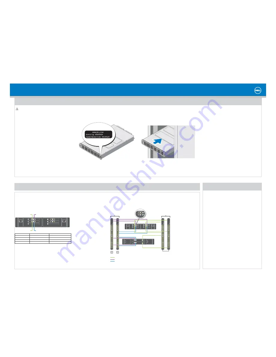
Locating Your System Service Tag
Your system is identified by a unique Express Service Code and Service Tag number.
•
The Express Service Code and Service Tag are located on the rack mounting
support bracket.
This information is used by Dell to route support calls to the appropriate personnel.
•
Installing the Solution in a Rack
Your solution requires a properly grounded electrical outlet, a compatible rack,
•
and a rack installation kit. For information about installing the rails for the
PowerVault NX3600/NX3610 solution, see the
Rack Installation Instructions that
shipped with your rack kit.
Rack the NX3600/NX3610 solution near the PowerVault MD Series array. Ensure
•
that the NAS iSCSI ports are on the same subnet as the MD Series array iSCSI ports.
Installation Guidelines
Depending on your configuration, use 14 Category 5E or Category 6 Ethernet cables
•
with RJ-45 connectors. Connect eight cables to the PowerVault NX3600/NX3610
solution and six cables to the MD storage array.
It is recommended that you use a minimum of four network switches as shown in
•
step 2.
NOTE:
The MD32
x0i storage array has four iSCSI data ports on each controller.
Do not use ports 2 and 3 on the controllers for FluidFS. These ports can be used for
block-level access from other hosts.
Required Settings on the SAN Switch
Jumbo Frames enabled (9216 MTU)
•
Port Fast enabled
•
Flow Control enabled
•
NOTE:
Dell PowerConnect switches must be con
fi
gured to 9216 MTU or greater to
accept frames of size 9000 MTU. Non-Dell switches may require a di
ff
erent MTU
con
fi
guration for similar frame sizes. For more information on MTU con
fi
guration for
non-Dell switches, see the related switch documentation.
NOTE:
Jumbo Frames and
fl
ow control settings are mandatory for all ports used solely
by the PowerVault NX3600/NX3610 solution and
fi
le access.
1
|
Racking Your Solution
2
|
Cabling Your Solution
Turn on the PowerVault MD storage array(s) and network switches.
1.
Verify if the network switches are con
fi
gured with the required settings.
2.
Turn on the NX3600/NX3610 solution.
3.
Preparing the Management Station
Connect the management station to the client switch.
1.
Verify that IPv6 is enabled.
2.
Verify that Java Runtime Environment (JRE) is installed on the management
3.
station.
Install the NAS Initial Deployment Utility (IDU) software.
4.
Download SSH client for CLI access.
5.
3
|
Turning On Your Solution
Network Cabling
SAN switches
client switches
PowerVault NX3600
controller 2
PowerVault MD storage array
client connections
SAN A connections
SAN B connections
Cabling Worksheet
SAN connection B
SAN connection A
client connection 1
client connection 2
PowerVault NX3600/NX3610
Controller 1
Controller 2
Client connection 1
To client switch
To client switch
Client connection 2
To client switch
To client switch
SAN connection A
To SAN switch (A)
To SAN switch (A)
SAN connection B
To SAN switch (B)
To SAN switch (B)
controller 1
NOTE:
The MD32
x
0i storage array has four iSCSI data ports on each con-
troller. Do not con
fi
gure ports 2 and 3 on the same subnets as the FluidFS
NAS system. They can be connected to the same switch for other clients,
but must be con
fi
gured on di
ff
erent subnets.
controller 2
controller 1


