background image

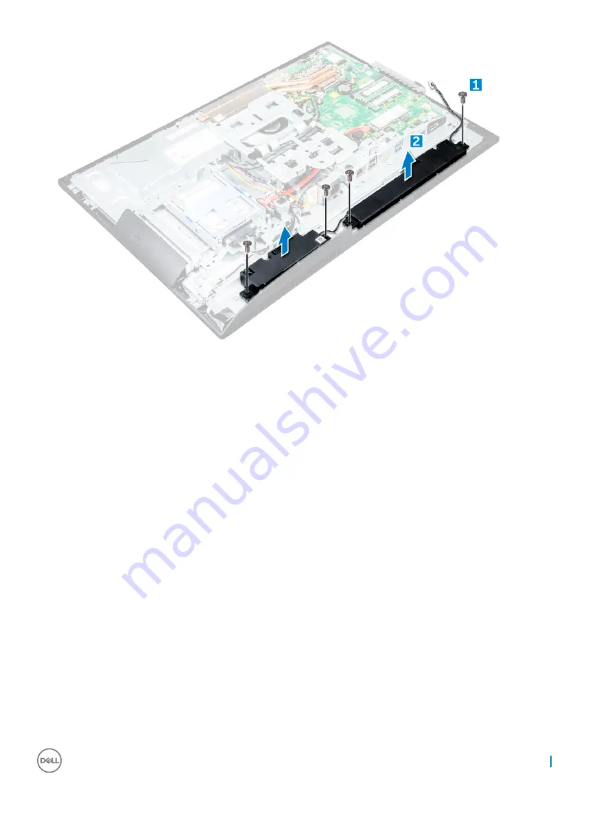
Installing the speaker module

Insert the speaker module into the slot on the chassis.

Tighten the screws to secure the speaker to the chassis.

Secure the speaker cables through the retention clips.

Connect the speaker cable to the connector on the system board.

Install the:

a

system board shield

b

speaker cover

c

back cover

d

cable cover

e

stand

Follow the procedure in 

After working inside your computer

.

Панель дисплея

Removing the display panel

Follow the procedure in 

Before working inside your computer

.

Remove the:

a

stand

b

back cover

c

cable cover

d

speaker cover

e

speaker

f

hard drive

Извлечение и установка компонентов

25

Summary of Contents for OptiPlex 5250

Page 1: ...Dell OptiPlex 5250 All In One Owner s Manual Regulatory Model W14B Regulatory Type W14B002 ...

Page 2: ...ния оборудования или потери данных и подсказывает как этого избежать ПРЕДУПРЕЖДЕНИЕ Пометка ПРЕДУПРЕЖДЕНИЕ указывает на риск повреждения оборудования получения травм или на угрозу для жизни Корпорация Dell или ее дочерние компании 2017 Все права защищены Dell EMC и другие товарные знаки являются товарными знаками корпорации Dell Inc или ее дочерних компаний Другие товарные знаки могут быть товарны...

Page 3: ...e back cover 12 Installing the back cover 13 Speaker cover 13 Removing the speaker cover 13 Installing the speaker cover 15 Жесткий диск 15 Removing the hard drive assembly 15 Installing the hard drive assembly 16 Оптический дисковод 16 Removing the optical drive assembly 16 Installing the optical drive assembly 17 System board shield 18 Removing the system board shield 18 Installing the system bo...

Page 4: ...Installing the converter board 34 Системный вентилятор 35 Removing the system fan 35 Installing the system fan 35 Intrusion switch 36 Removing the intrusion switch 36 Installing the intrusion switch 37 Power and On Screen Display OSD buttons board 37 Removing the power and On Screen Display OSD buttons board 37 Installing the power and OSD buttons board 38 Процессор 38 Removing the processor 38 In...

Page 5: ...тры экрана управления потреблением энергии 61 POST behavior screen options 62 Параметры экрана поддержки виртуализации 63 Параметры экрана обслуживания 63 Параметры экрана журнала системы 64 Updating the BIOS 64 Обновление BIOS с использованием флэш накопителя USB 65 Системный пароль и пароль программы настройки 65 Назначение системного пароля и пароля программы настройки 66 Удаление и изменение с...

Page 6: ...rds specifications 75 Display specifications 75 Drives specifications 75 Port and connector specifications 75 Параметры питания 76 Технические характеристики камеры дополнительно 76 Технические характеристики подставки 76 Physical specifications 76 Environmental specifications 77 8 Обращение в компанию Dell 78 6 Contents ...

Page 7: ...сности прилагаемые к компьютеру Для замены компонента или установки отдельно приобретенного компонента выполните процедуру снятия в обратном порядке ПРЕДУПРЕЖДЕНИЕ Отсоедините компьютер от всех источников питания перед снятием крышки компьютера или панелей После окончания работы с внутренними компонентами компьютера установите все крышки панели и винты на место перед тем как подключить компьютер к...

Page 8: ...ластиковая палочка Выключение компьютера Выключение компьютера Windows 7 ПРЕДОСТЕРЕЖЕНИЕ Во избежание потери данных сохраните и закройте все открытые файлы и выйдите из всех открытых программ перед выключением компьютера 1 Нажмите кнопку Пуск 2 Щелкните Завершение работы ПРИМЕЧАНИЕ Убедитесь что компьютер и все подключенные к нему устройства выключены Если компьютер и подключенные устройства не вы...

Page 9: ...йству а затем к компьютеру 3 Подключите компьютер и все внешние устройства к электросети 4 Включите компьютер 5 При необходимости проверьте исправность работы компьютера запустив программу ePSA Diagnostics Диагностика ePSA Важная информация ПРИМЕЧАНИЕ Не используйте сенсорный экран в пыльных жарких местах и при условиях повышенной влажности ПРИМЕЧАНИЕ Перепады температуры могут привести к образова...

Page 10: ...and 1 Follow the procedure in Before working inside your computer 2 Place the computer on a flat surface with the display facing downward 3 To remove the stand a Press the tab on the cover to release the stand 1 b Lift the stand upward 2 NOTE There are optional stands available but they will attach in a similar manner 2 10 Извлечение и установка компонентов ...

Page 11: ...uter 2 Remove the stand 3 To remove the cable cover a Remove the screw that secures the cable cover to the computer 1 b Push the release tabs to release the cable cover 2 c Lift the cable cover away from the computer 3 Installing the cable cover 1 Align the notches on the cable cover to the holes on the computer and press the cable cover until it snaps in 2 Tighten the screw to secure the cable co...

Page 12: ...moving the back cover 1 Follow the procedure in Before working inside your computer 2 Remove the a stand b cable cover 3 Pry the edges of the back cover from the bottom to release it from the computer 4 Lift the back cover from the computer 12 Извлечение и установка компонентов ...

Page 13: ...ll the a cable cover b stand 3 Follow the procedure in After working inside your computer Speaker cover Removing the speaker cover 1 Follow the procedure in Before working inside your computer 2 Remove the a stand b cable cover c back cover 3 Remove the screws that secure the speaker cover to the computer Извлечение и установка компонентов 13 ...

Page 14: ...4 Pull and remove the speaker cover from the computer NOTE To avoid damage to the back cover release it from the pull tabs 14 Извлечение и установка компонентов ...

Page 15: ...re in After Working Inside Your Computer Жесткий диск Removing the hard drive assembly 1 Follow the procedure in Before working inside your computer 2 Remove the a stand b back cover 3 To remove the hard drive assembly a Press the tab on the bracket and slide the hard drive assembly until the tabs are released from either side of the assembly 1 b Slide the hard drive assembly upwards to remove it ...

Page 16: ...gned then slide the Hard Drive assembly until the tab locks into the cage 3 Install the a back cover b stand 4 Follow the procedure in After working inside your computer Оптический дисковод Removing the optical drive assembly 1 Follow the procedure in Before working inside your computer 2 Remove the a stand b back cover 3 To remove the optical drive assembly a Press the securing tab at the base of...

Page 17: ...ay from the optical drive 2 Installing the optical drive assembly 1 Place the bracket to align the screw holders on the optical drive 2 Tighten the screws to secure the bracket to the optical drive 3 Insert the optical drive assembly into the drive slot until it snaps in 4 Install the Извлечение и установка компонентов 17 ...

Page 18: ...puter 2 Remove the a stand b back cover 3 To remove the system board shield a Press the securing tab to release the system board shield from the slots on the computer 1 b Slide the system board shield away from the computer 2 Installing the system board shield 1 Align and slide the system board shield until it snaps in 2 Install the a back cover b stand 18 Извлечение и установка компонентов ...

Page 19: ...To remove the memory module a Pry the retention clips away from the memory module until it pops up 1 b Lift the memory module from the connector 2 Installing the memory module 1 Insert the memory module on the memory connector until the clips secure the memory module 2 Install the a system board shield b back cover c stand 3 Follow the procedure in After working inside your computer Извлечение и у...

Page 20: ...d a Remove the screw that secures the SSD card to the computer 1 b Lift the SSD card away from the connector 2 Installing the SSD card 1 Insert the SSD card into the connector 2 Tighten the screw to secure the SSD card to the system board 3 Install the a system board shield b back cover c stand 4 Follow the procedure in After working inside your computer 20 Извлечение и установка компонентов ...

Page 21: ... shield 3 Press the latch to release the coin cell battery and remove it from the computer Installing the coin cell battery 1 Insert the coin cell battery into the slot on the system board until it fits securely 2 Install the a system board shield b back cover c stand 3 Follow the procedure in After working inside your computer Извлечение и установка компонентов 21 ...

Page 22: ...es the WLAN card to the system board 2 c Hold the WLAN card and pull it from the connector on the system board 3 Installing the WLAN card 1 Align the WLAN card to the connector on the system board 2 Tighten the screw to secure the WLAN card to the system board 3 Connect the antenna cables to the connectors on the WLAN card 4 Install the a system board shield b back cover c stand 5 Follow the proce...

Page 23: ...the screws that secure the heat sink to the chassis 1 2 b Lift the heat sink away from the computer 3 Installing the heat sink 1 Align and place the heat sink in the slot 2 Tighten the screws to secure the heat sink to the computer 3 Install the a system board shield b back cover c stand 4 Follow the procedure in After working inside your computer Извлечение и установка компонентов 23 ...

Page 24: ...m board shield 3 To release the speaker module a Disconnect the speaker cable from the connector on the system board 1 b Unthread the speaker cables from the retention clips 2 4 To remove the speaker module a Remove the screws that secure the speaker module to the chassis 1 b Lift the speaker module and remove it from the chassis 2 24 Извлечение и установка компонентов ...

Page 25: ...er cable to the connector on the system board 5 Install the a system board shield b speaker cover c back cover d cable cover e stand 6 Follow the procedure in After working inside your computer Панель дисплея Removing the display panel 1 Follow the procedure in Before working inside your computer 2 Remove the a stand b back cover c cable cover d speaker cover e speaker f hard drive Извлечение и ус...

Page 26: ...3 To remove the display panel a Remove the screws that secure the display panel to the bezel 1 b Lift the display panel away from the bezel 2 Installing the display panel 1 Align the display panel with the screw holes on the computer 2 Tighten the screws to secure the display panel to the computer 3 Install the a chassis frame b system board c power supply unit 26 Извлечение и установка компоненто...

Page 27: ...sis frame NOTE These instructions are applicable only for systems with a non touch screen display 1 Follow the procedure in Before working inside your computer 2 Remove the a stand b back cover c cable cover d speaker cover e speaker f hard drive g optical drive h VESA mount bracket i system board shield j SSD card k WLAN card l memory m heat sink n system fan o processor p coin cell battery q pow...

Page 28: ... Display Bezel for the Power Button board below the OSD Button board Trying to lift the chassis frame without disconnecting this cable first could damage the connector a Remove the screws that secure the chassis frame to the computer 1 NOTE Chassis frame screws have M3 stamped next to them b Lift the chassis frame away from the computer 2 28 Извлечение и установка компонентов ...

Page 29: ...he cables through the retention clips 4 Install the a system board b power supply unit c coin cell battery d system fan e processor f heat sink g memory h WLAN card i system board shield j SSD card k VESA mount bracket l optical drive m hard drive n cable cover o speaker p speaker cover q back cover r stand Извлечение и установка компонентов 29 ...

Page 30: ...tion clips in the chassis 1 b Disconnect the power supply cable from the connector on the system board 2 NOTE Press lock clip to release the power supply cable from the system board 4 To release the PSU NOTE There is an additional cable retention clip on the side of the VESA mount bracket The PSU near that is not visible in the removing cables from retention clips image a Remove the screw that sec...

Page 31: ...5 To remove the PSU a Remove the screw that secure the PSU to the chassis 1 b Slide the PSU and lift it away from the chassis 2 Извлечение и установка компонентов 31 ...

Page 32: ... the system board 7 Install the a system board shield b speaker cover c cable cover d back cover e stand 8 Follow the procedure in After working inside your computer VESA mount bracket Removing the VESA mount bracket 1 Follow the procedure in Before working inside your computer 2 Remove the a stand b back cover c cable cover d speaker cover e system board shield f power supply unit 3 To remove the...

Page 33: ...ly unit b system board shield c speaker cover d cable cover e back cover f stand 4 Follow the procedure in After working inside your computer Converter board Removing the converter board 1 Follow the procedure in Before working inside your computer 2 Remove the a stand b back cover c cable cover d speaker cover e system board shield f power supply unit Извлечение и установка компонентов 33 ...

Page 34: ... from the computer 4 Installing the converter board 1 Place the convertor board in the slot 2 Tighten the screws to secure the converter board to the chassis 3 Connect the converter board cable and display backlight cable to the connectors on the converter board 4 Install the a VESA mount bracket b power supply unit c system board shield d speaker cover e cable cover f back cover g stand 5 Follow ...

Page 35: ...A mount bracket 3 To remove the system fan a Disconnect the system fan cable from the connector on the system board 1 b Remove the screws that secure the system fan to the computer 2 c Lift the system fan away from the computer 3 Installing the system fan 1 Align and place the system fan in the slot on the chassis 2 Tighten the screws to secure the system fan to the system board Извлечение и устан...

Page 36: ... Before working inside your computer 2 Remove the a stand b back cover c cable cover d speaker cover e system board shield f power supply unit g VESA mount bracket 3 To remove the intrusion switch a Disconnect the intrusion switch cable from the connector on the system board 1 b Unthread the intrusion switch cable from the retention clips on the computer 2 c Remove the screw that secures the intru...

Page 37: ...edures in After working inside your computer Power and On Screen Display OSD buttons board Removing the power and On Screen Display OSD buttons board 1 Follow the procedure in Before working inside your computer 2 Remove the a stand b back cover 3 To remove the power and OSD buttons board a Remove the screw to remove the metal plate that secures the power and OSD buttons board to the computer 1 b ...

Page 38: ...r and OSD buttons board 5 Tighten the screw to secure the power and OSD buttons board 6 Install the a back cover b stand 7 Follow the procedure in After working inside your computer Процессор Removing the processor 1 Follow the procedure in Before working inside your computer 2 Remove the a stand b back cover c cable cover d speaker cover e speaker f VESA mount bracket g system board shield 38 Изв...

Page 39: ...the processor contacts Touch only the side edges of the processor Installing the processor 1 Align the processor with the socket keys CAUTION Do not use force to seat the processor When the processor is positioned correctly it engages easily into the socket 2 Align the pin 1 indicator of the processor with the triangle on the socket 3 Place the processor on the socket such that the slots on the pr...

Page 40: ...al drive h VESA mount bracket i system board shield j SSD card k WLAN card l memory m heat sink n system fan o processor p coin cell battery q power supply unit 3 Disconnect the following cables from the system board a display 1 b system fan 2 c SATA 3 d side button cable 4 e intrusion switch hard drive and optical drive 5 f speaker 6 g camera and microphone 7 40 Извлечение и установка компонентов...

Page 41: ...4 Remove the screws that secure the system board to the chassis Извлечение и установка компонентов 41 ...

Page 42: ...5 Slide and lift the system board to remove it from the computer 42 Извлечение и установка компонентов ...

Page 43: ...he base panel 4 Install the a power supply unit b coin cell battery c system fan d processor e heat sink f memory g WLAN card h SSD card i system board shield j VESA mount bracket k optical drive l hard drive m cable cover n speaker o speaker cover p back cover q stand 5 Follow the procedure in After working inside your computer Извлечение и установка компонентов 43 ...

Page 44: ...2 SSD slot 11 Optical drive connector 12 Intrusion switch connector 13 Hard drive connector 14 Side buttons connector 15 Touchpad connector 16 CAC PIV connector reserved 17 Converter board connector 18 Windows serial debug connector 19 HDD ODD power connector 20 LPC debug connector 21 APS debug connector 22 Power supply connector 23 CPU fan connector 24 CPU socket 44 Извлечение и установка компоне...

Page 45: ...ce Uses Intel s revolutionary new storage technology 3D XpointTM memory media Ultra low latency exceptional responsiveness Performance saturation at queue depth of 4 and lower Very high endurance capabilities Intel OptaneTM Memory Module Driver Requirements The following table describes the driver requirements for the Intel OptaneTM memory system acceleration us a component of Intel Rapid Storgae ...

Page 46: ...uter c Tighten the screw that secures the M 2 Intel optane memory module on the computer Product specifications Features Specification Capacities 16 GB 32 GB Expansion cards PCIe 3 0 x 2 M 2 form factors all densities 2280 S3 B M 46 M 2 Intel Optane Memory Module 16 GB ...

Page 47: ...Express 1 1 PCI Express Base specifiation rev 3 0 PCI M 2 HS Spec Certification and Declarationsµ UL CE C Tick BSMI KCC Microsoft WHQL Microsoft WHCK VCCI Endurance Rating 100 GB Writes per day Upto 182 3 TBW Terabytes written Temperature Specification Operating 0 to 70º C Non Opearting 10 to 85º C Temperature monitoring Shock 1500 G 0 5msec Vibration Operating 2 17 GRMs 5 800Hz Non Operating 3 13...

Page 48: ...on assume the device is mounted securely with the input vibration applied to the drive mounting screws Stimulus may be applied in the X Y or Z axis shock specification is measured using Root Mean Squared RMS value 5 Vibration specifications assume the device is mounted securely with the input vibration applied to the drive mounting screws Stimulus may be applied in the X Y or Z axis Vibration spec...

Page 49: ...rst time boot up the system will scan the pairing status as below screen shot after shutdown It s working as designed and the message will not appear again in following boot ups M 2 Intel Optane Memory Module 16 GB 49 ...

Page 50: ... Flash 2 5 500 GB SATA 7200 RPM Self Encrypting Drive OPAL FIPS 2 5 1 0 TB SATA 7200 RPM Hard Disk Drive 2 5 1 0 TB SATA 5400 RPM Solid State Hybrid Drive w 8GB Flash 2 5 2 0 TB SATA 5400 RPM Hard Disk Drive Solid State Drives SSD Table 4 SSD 2 5 256 GB SATA Solid State Drive Class 20 2 5 512 GB SATA Solid State Drive Class 20 M 2 128 GB SATA Solid State Drive Class 20 M 2 256 GB PCIe NVMe Solid S...

Page 51: ...x 2GB Linux operating system only 4GB DDR4 2400MHz 1 x 4GB 8GB DDR4 2400MHz 1 x 8GB 8GB DDR4 2400MHz 2 x 4GB 16GB DDR4 2400MHz 2 x 8GB 32GB DDR4 2400MHz 2 x 16GB NOTE If this computer is purchased with Intel 6th Generation CPUs the maximum MHz the computer can achieve is 2133 Проверка системной памяти в Windows 10 и Windows 7 Windows 10 1 Нажмите кнопку Windows и выберите All Settings Все настройк...

Page 52: ...ADDR 1 CMD ADDR VREFDQ Now Internal tCK DLL Enabled 300 Mhz 800 Mhz 667Mhz 1 6Ghz Higher data rates tCK DLL Disabled 10MHz 125MHz optional Undefined to 125MHz DLL off now fully supported Read Latency AL CL AL CL Expanded values Write Latency AL CWL AL CWL Expanded values DQ Driver ALT 40 Omega 48 Omega Optimal for PtP Applications DQ Bus SSTL15 POD12 Less I O Noise and Power RTT Values in Omega 12...

Page 53: ...otch location on the DDR4 is slightly different to prevent the module from being installed into an incompatible board or platform Figure 1 Notch difference Increased thickness DDR4 modules are slightly thicker than DDR3 to accommodate more signal layers Figure 2 Thickness difference Curved edge DDR4 modules feature a curved edge to help with insertion and alleviate stress on the PCB during memory ...

Page 54: ...ьность загрузки позволяет пользователям обойти установленную последовательность загрузки с устройств и выполнить загрузку сразу с выбранного устройства например c оптического или жесткого диска Во время самотестирования при включении питания POST пока высвечивается логотип Dell вы можете сделать следующее Войти в программу настройки системы нажатием клавиши F2 Вызвать меню однократной загрузки наж...

Page 55: ...устройств указанные в данном разделе пункты меню могут отсутствовать General screen options This section lists the primary hardware features of your computer Option Description System Information This section lists the primary hardware features of your computer System Information Displays BIOS Version Service Tag Asset Tag Ownership Tag Ownership Date Manufacture Date and the Express Service Code ...

Page 56: ...features to use NICs that are enabled This may be used without PXE turned on When you enable Enabled w PXE the type of PXE boot Legacy PXE or UEFI PXE depends on the current boot mode and type of option ROMs in use The UEFI Network Stack is required in order to have UEFI PXE functionality fully enabled Enabled UEFI Network Stack This option is disabled by default Allows you to configure the integr...

Page 57: ...NOTE USB keyboard and mouse always work in the BIOS setup irrespective of these settings Side USB Configuration This field allows you to enable or disable side USB ports Side Port1 Top Side Port2 Bottom Rear USB Configuration This field allows you to enable or disable rear USB ports Rear Port Rear Right Rear Port 2 Front Right Rear Port 3 Rear Left Rear Port 4 Front Left Audio This field enables o...

Page 58: ...gth of Administrator and System passwords Password Bypass Allows you to enable or disable the permission to bypass the System and the Internal HDD password when they are set The options are Disabled Reboot bypass Default setting Disabled Password Change Allows you to enable the disable permission to the System and Hard Drive passwords when the admin password is set Default setting Allow Non Admin ...

Page 59: ...s you to enable or disable the option to enter setup when an admin password is set Enable Admin Setup Lockout This option is disabled by default Master Password Lockout If enabled this option disables the master password support The Hard Disk passwords need to be cleared before the setting can be changed Default setting Disabled Параметры экрана безопасной загрузки Функция Описание Secure Boot Ena...

Page 60: ...лчанию Параметры расширений Intel Software Guard Параметр Описание Intel SGX Enable Позволяет включать или отключать защитные расширения программного обеспечения Intel с целью обеспечения безопасной среды для выполнения кода хранения конфиденциальных данных в контексте основной операционной системы Disabled Отключено по умолчанию Enabled Включено Enclave Memory Size Позволяет задать объем резервно...

Page 61: ...ать время автоматического включения питания компьютера Доступные параметры Disabled Отключено Every Day Каждый день Weekdays В рабочие дни Select Days Выбрать дни Значение по умолчанию Disabled Отключено ПРИМЕЧАНИЕ Эта функция не работает если компьютер выключается с помощью выключателя удлинителя или сетевого фильтра либо если функции Auto Power задано значение Disabled Отключено Deep Sleep Contr...

Page 62: ...ST behavior screen options Option Description Numlock LED Specifies if the NumLock function can be enabled when the system boots This option is enabled by default Keyboard Errors Specifies whether keyboard related errors are reported when it boots This option is enabled by default Fastboot Allows you to speed up the boot process by bypassing some of the compatibility steps The options are Minimal ...

Page 63: ...низма сообщений о системных ошибках SERR BIOS Downgrade Управление откатом системного микропрограммного обеспечения до предыдущих версий Очистка данных Очистка данных при следующей загрузке Восстановление BIOS Восстановление BIOS с жесткого диска Следуйте инструкциям для восстановления BIOS с жесткого диска 1 Включите питание системы 2 Во время отображения синего логотипа Dell нажмите клавишу F2 д...

Page 64: ...u cannot find your Service Tag click Detect My Product Proceed with the instructions on screen 4 If you are unable to locate or find the Service Tag click the Choose from all products 5 Choose the Products from the list NOTE Choose the appropriate category to reach the product page 6 Select your computer model and the Product Support page of your computer appears 7 Click Get drivers and click Driv...

Page 65: ...новление BIOS 4 Перезапустите систему и при появлении логотипа Dell нажмите клавишу F12 чтобы открыть меню однократной загрузки 5 С помощью клавиш со стрелками перейдите к пункту USB Storage Device USB накопитель и нажмите клавишу ВВОД 6 При загрузке системы появится командная строка Diag C 7 Введите полное имя файла например O9010A12 exe и нажмите клавишу ВВОД 8 Будет загружена служебная программ...

Page 66: ...ание только следующих специальных знаков пробел 3 Введите системный пароль который вы вводили ранее в поле Confirm new password Подтвердите новый пароль и нажмите кнопку OK 4 Нажмите Esc появится сообщение с запросом сохранить изменения 5 Нажмите Y чтобы сохранить изменения Компьютер перезагрузится Удаление и изменение существующего системного пароля или пароля настройки системы Убедитесь что пара...

Page 67: ...дите новый пароль Если вы удаляете системный пароль или пароль настройки системы при запросе подтвердите удаление 5 Нажмите Esc появится сообщение с запросом сохранить изменения 6 Нажмите Y чтобы сохранить изменения и выйти из программы настройки системы Компьютер перезагрузится Настройка системы 67 ...

Page 68: ...рами может привести к неверным результатам или сообщениям об ошибках ПРИМЕЧАНИЕ Для некоторых проверок определенных устройств требуется участие пользователя Обязательно убедитесь что у терминала компьютера во время выполнения диагностических проверок Запуск диагностики ePSA 1 Включите питание компьютера 2 Во время загрузки нажмите клавишу F12 при появлении логотипа Dell 3 На экране меню загрузки в...

Page 69: ...mode Customers can test the health of the power system by pressing the test button The button is lit by a signal in the power supply called Power_Good PG When the 3 3v 5v and 12v rails are up and within spec the PG signal turns on lighting the self test LED By removing the cable harness in units that do not pass this test the customer or technician can isolate the failure s cause to an attached de...

Page 70: ...70 Поиск и устранение неполадок ...

Page 71: ...ему Длительность теста составляет приблизительно 20 секунд за это время на экране дважды отобразится последовательность цветных полос Чтобы включить тестирование BIST с помощью кнопки переключения экранного меню сделайте следующее 1 Нажмите и удерживайте кнопку переключения экранного меню 2 Нажмите кнопку питания чтобы включить компьютер удерживая при этом нажатой кнопку переключения экранного мен...

Page 72: ...с помощью команд BIOS Режим BIST будет работать приблизительно в течение 20 секунд за это время на экране дважды отобразится проверочная последовательность цветных полос Длительностью проверки управляет BIOS По истечении заданного промежутка времени BIOS вернет систему в меню ePSA 72 Поиск и устранение неполадок ...

Page 73: ... specifications Environmental specifications Processors Processor numbers are not a measure of performance Processor availability is subject to change and may vary by region or country The following table lists the processors that are supported in OptiPlex 5250 AIO Feature Specification Processor type NOTE 7th generation Intel processors support Windows 10 Linux only 6th generation Intel processor...

Page 74: ...and 16 GB Memory connectors two internally accessible DDR4 SODIMM sockets Minimum memory 2 GB Maximum memory 32 GB Video specifications Feature Specification Video Controller Integrated Intel HD 630 610 530 510 Graphics Optional AMD Radeon M465 2GB Video Memory shared memory External display support DisplayPort HDMI in and HDMI out Optional only on FHD model configuration 7450 AIO Audio specificat...

Page 75: ... specifications Features Specification Network adapter Intel 10 100 1000 Mbps RJ 45 Ethernet Wireless Combo M 2 card Intel Wireless 8265 M 2 PCIe WLAN card 802 11n ac with Bluetooth Cards specifications Feature Specification M 2 slots One SSD 256GB Encrypted SED opal 2 SATAA3 M 2 22mm 80mm 2 38mm 512MB Multi Level Cell Hynix SSD 256GB SATA3 M 2 22mm 80mm 2 38mm LiteOn Display specifications Drives...

Page 76: ... более 2 6 А нижний диапазон напряжения Не более 1 3 А верхний диапазон напряжения Технические характеристики камеры дополнительно Элемент Технические характеристики Разрешение изображения 2 0 мегапикселей Видеоразрешени е FHD 1080p Угол обзора по диагонали 74 градуса Технические характеристики подставки Элемент Технические характеристики Наклон 5 30 градусов Physical specifications Feature Specif...

Page 77: ... to 35 C 32 F to 95 F Storage 40 C to 65 C 40 F to 149 F Relative humidity maximum Specifications Operating 20 to 80 non condensing Storage 20 to 80 non condensing Maximum vibration Specifications Operating 0 26 GRMS at 5 to 350 Hz Storage 1 37 GRMS at 5 to 200 Hz Maximum shock Specifications Operating 40 G Storage 105 G Altitude maximum Specifications Operating 0 m to 5000 m 0 ft to 16 404 ft Non...

Page 78: ...ется по странам и видам продукции и некоторые службы могут быть недоступны в вашем регионе Порядок обращения в компанию Dell по вопросам сбыта технической поддержки или обслуживания пользователей описан ниже 1 Перейдите на веб узел Dell com support 2 Выберите категорию поддержки 3 Укажите свою страну или регион в раскрывающемся меню Choose a Country Region Выбор страны региона в нижней части стран...

Reviews: